45 ge rr7 relay wiring diagram
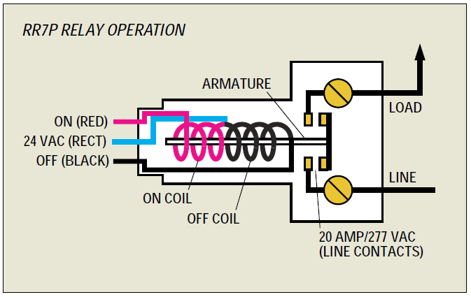
GE Current - RR7 - Platt Electric Supply GE Current RR7 The GE Model RR-7 lighting relays is a mechanical latching-type unit designed for building automation systems. Each relay requires only momentary 24 volt AC switch circuit pulses to open or close line voltage circuits. All GE low voltage relays may be used to full-rated capacity for tungsten filament, ballast, or resistive loads. PDF Lighting Controls LIGHTING CONTROLS LIGHTING CONTROLS GE LIGHTING RELAYS MODELS RR-7, RR-9 382 2004 KELE CATALOG • • USA 888-397-5353 • International 901-382-6084 The relay employs a split low-voltage coil to move the line voltage contact armature to the on or off latched position.
RR-7, RR-9 | GE Mechanical Latching 24 VAC Lighting Relays ... GE Model RR-7 and RR-9 lighting relays are mechanical latching-type units requiring only momentary 24 VAC switch circuit pulses to open or close line voltage circuits. All GE low voltage relays may be used to full-rated capacity for tungsten filament, ballast, or resistive loads. The Model RR-9 includes an auxiliary contact on the low voltage side for status indication.
Ge rr7 relay wiring diagram
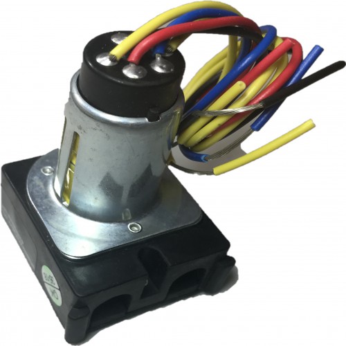
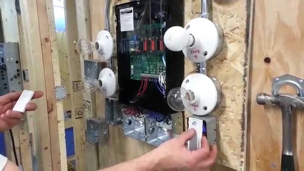
GE RR7PBP - 20A SPST Low Voltage Relay GE RR7PBP (replacement for RR7P) Rated 20 amp, 277 volt, 5-pin plug end can be snipped off for use in non-digital panels. Suitable for use on circuit capable of delivering not more than 10 kA Sym. Amps, 277 Maximum. SPST (single pole single throw) maintained mechanical relay module, 6" wire leads. 1.5" W x 1.75" D x 2.5" H; 7/8" diameter cylinder. GE Low voltage relay system - YouTube Found the relays it was in a room where I forgot to check the first time. Found the relays it was in a room where I forgot to check the first time. Rr7 Relay Wiring Diagram Rr7 Relay Wiring Diagram RR7 Sensors: How Can I Troubleshoot GE RR7 Relays And Sensor Switch You should measure about VDC at the red and black wires of the sensor. This makes remote switching of lighting circuits . RR7. Standard 3-wire relay with stripped leads. RR8. Pilot contact 4-wire relay with stripped leads. RR9. GE RR7 low voltage relay.
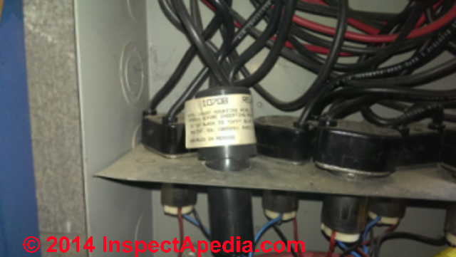
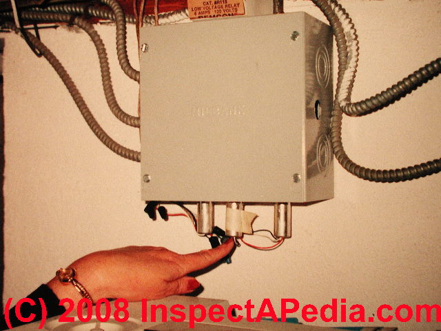
Ge rr7 relay wiring diagram. Ge Rr7 Relay Diagram - Wiring Diagram Pictures The GE RR7 low voltage relay is a direct. GE low voltage wiring switches, relays and junction box (C) InspectAPedia . See Three-wire to Touch-Plate® Wiring Diagram. 28VDC latching relay, whereas the the GE® relay (RR-7) is a dual coil, 24VAC latching relay, and the Remcon®.The relay should "click" and the Relay Indicator should change state. Ge Rr4 Relay Wiring Diagram diagrams rr7 relay wiring diagram ge at, flasher relay wiring diagram carlplant with, 12v relay wiring diagram carlplant inside, 30a 5 wire relay wiring pin diagram driving lights inside 12 volt at, how to wire a relay 5pin and 4pin bosch style youtube relay best wiring diagram, phase controller wiring failure relay diagram electrical inside, 5. saredumatsukiko.com › category › follower-episodeクソ旦那への逆襲 : され妻つきこブログ|アラサーママのサレ妻経験録 Powered by... Jul 12, 2021 · サレ妻さくらこさんの経験談「クソ旦那への逆襲」の 漫画版の連載がスタート! この度、お友達のさくらこさんの漫画も、つきこのブログで掲載させていただく運びとなりました! Ge Low Voltage Switch & Relay Wiring Instruction Guide ... GEL-WIRING View Details exclusive instructions for installing newer GE RS2 series low voltage switches in remote control wiring systems using RR7 RR8 or RR9 mechanical relays and RT series transformers55. For private use only - no sharing or posting. Do not connect any single low. 12v relay wiring diagram ge lighting.
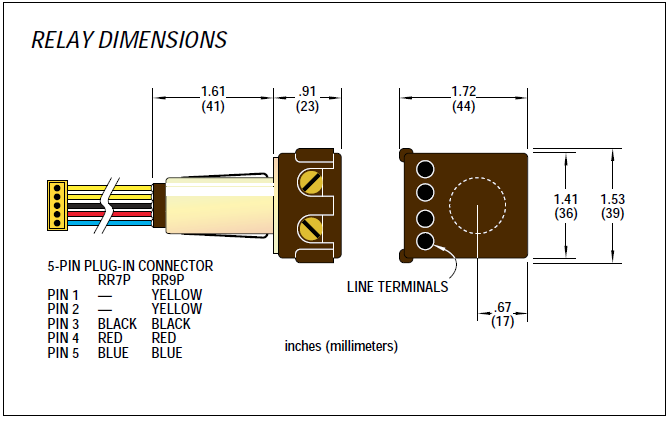
Problem with GE RR7 low voltage relay. | Terry Love ... My son didn’t get a chance to see how the light was connected to the GE RR7 relay installed in the connection box. He was able to replace the light connected to another low voltage relay since the original light was still there, but, is having problems with the RR7 relay to which no light was connected. The two relays seem different. PDF Remote Control Low Voltage Switching RR9P Isolated pilot contact 5-wire relay with 5-pin connector The RR7P and RR9P relays are designed for simple connection to TLC panels. Other relay wire terminations are available, including: RR7 Standard 3-wire relay with stripped leads RR8 Pilot contact 4-wire relay with stripped leads RR9 Isolated pilot contact 5-wire relay with stripped leads GE Low Voltage Switch & Relay Wiring Instruction Guide Description. Read this Kyle Switch Plates exclusive instructions for installing newer GE RS2 series low voltage switches in remote control wiring systems using RR7, RR8 or RR9 mechanical relays and RT series transformers. Included for free with the purchase of any GE low voltage lighting component. Kyle Switch Plates is the premiere choice for ... GE RR7 Low Voltage Remote Control Relay Switch RR7P3 The GE RR7PBP low voltage relay is a direct replacement for older GE brand RR2, RR3, RR5, and RR7 mechanical latching relays. Like the original models, the RR7PBP is a standard solenoid relay designed for use with GE RS series unlighted switches. Generally, the red was for on, the black for off, and the blue was the common.
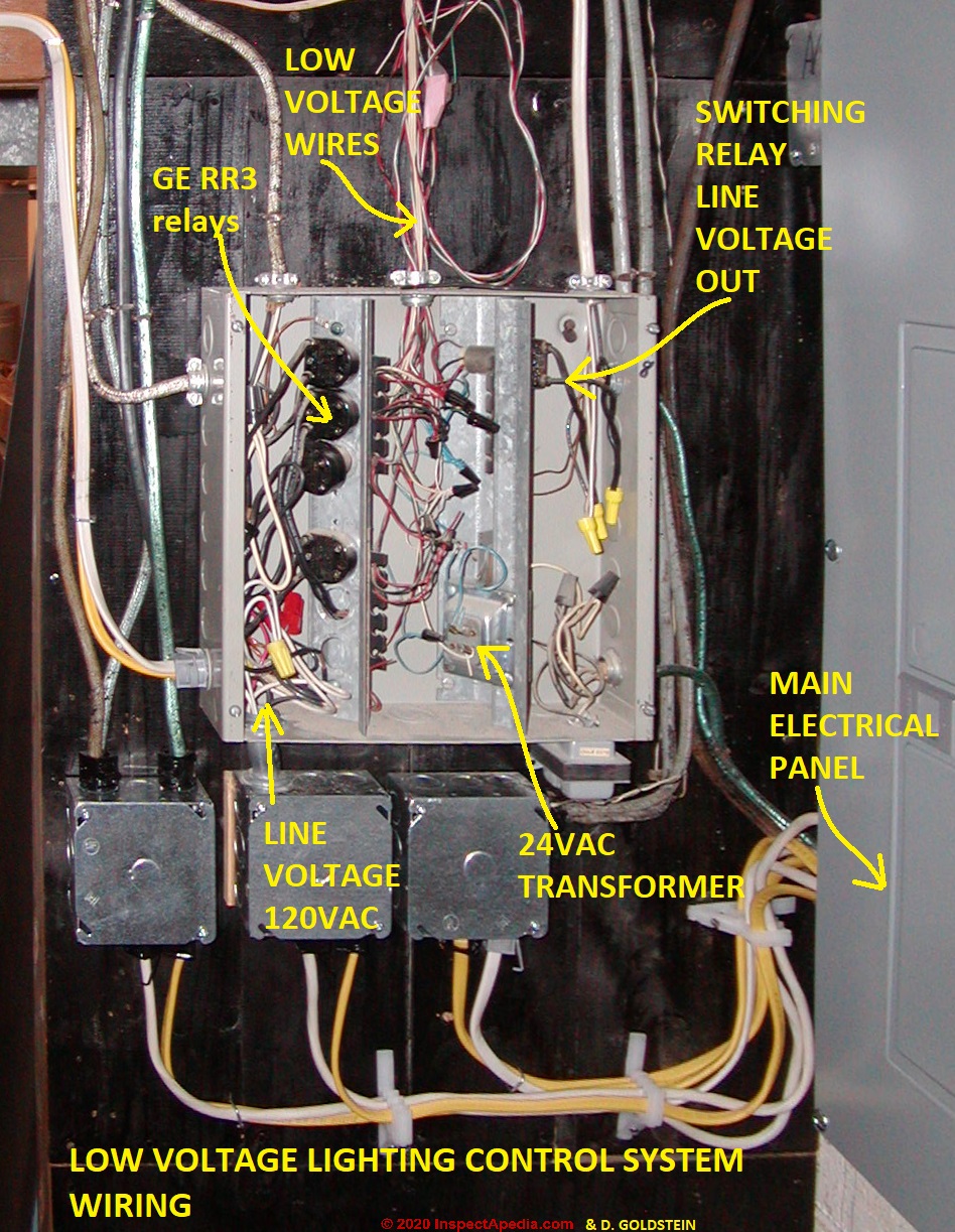
Ge Rr8 Relay Wiring Diagram Collection - Wiring Diagram Sample Name: ge rr8 relay wiring diagram - Ge Rr7 Wiring Diagram Relay 5 Pin Wiring Diagram Co Co Relay Remote; File Type: JPG; Source: suaiphone.org; Size: 153.74 KB; Dimension: 990 x 728; What's Wiring Diagram. A wiring diagram is a schematic which uses abstract pictorial symbols to show all of the interconnections of components in a very system. LIGHTING CONTROLS - InspectAPedia GE Model RR-7 and RR-9 Lighting Relays are mechanical latching-type units requiring only ... age circuits. All GE low voltage relays may be used to.2 pages PDF 2R7 & 2R9 Relay Operational Summary 2R7 and 2R9 split coil relay's unique con-struction has only one movable part (the contacts). This reliable relay design has a proven failure rate of less than .001 per-cent. It offers both the popular GE RR7 relay footprint and functionality (3 wire control) along with extreme reliability. The following describes the actual inter- LIGHTING CONTROLS - Kele 3 or 5 Control wires - 6", 20 AWG ... GE Model RR-7 and RR-9 lighting relays are mechanical ... circuit pulses to open or close line voltage circuits.2 pages
Low Voltage Relays in Lighting Systems Low Voltage relays ...
GEA-11082.pdf - Online Library of Electrical Part Manuals Basic Circuits and Applications ... Thus, installing a Remote Control component ... G E relays ( R R 7, R R 8, R R 9) are mechanical latching-type units.30 pages

How does a RR7 relay work? – Greedhead.net
General Electric Ge Rr7 Remote Control 21-30v-ac Relay Buy GENERAL ELECTRIC GE RR7 REMOTE CONTROL 21-30V-AC RELAY: Parts & Accessories ... Nilight 50003R Automotive Set 5-Pin 30/40A 12V SPDT with Interlocking Relay Socket and Wiring Harness-5 Pack, 2 Years Warranty 2,307. $13.50 $ 13. 50. Appliances › Parts & Accessories See All Buying Options . Share. Image Unavailable ...
Lighting & Electrical > Light Control Systems > Light Control ...
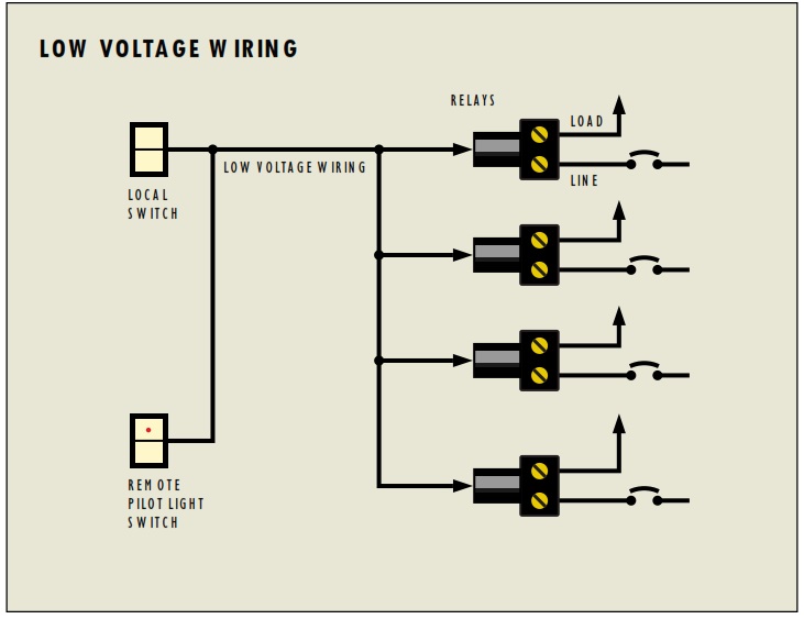
I have low voltage wiring using GE rr7 relays. there are ... Here's how it works: The GE RR7 relay is a 'latching relay'. This simply means that when you touch a light switch to turn on a light, it sends a pulse of low voltage (24 volts DC) to the relay on the RED wire and latches it ON for the light to be switched on by the relay. It requires a pulse of voltage on the BLACK wire to turn it OFF.

Lighting & Electrical > Light Control Systems > Light Control ...
rr7 ge relay wiring diagram - Wiring Diagram Rr7 Ge Relay Wiring Diagram. Free pdf search results latching relay i have a ge low voltage remote rr7 with blue black red wire am replacing the ceiling fan another light relays in lighting systems to control lights or motors system 24 emergency ul924 rated 277v contactor coil and an 8 group input module 48 capacity interior kele com controls ...

fuel FORD KUGA 2011 1.G Wiring Diagram Owner's Manual (655 Pages)
Fabulous Ge Rr7 Relay Modern House Wiring Diagram Lot of 3 general electric rr7 relay ge rr 7. washing machine capacitor wiring diagram wire a receptacle from a light switch wiring stepper motor to arduino wiring up a fuse box wiring a horse trailer wiring a ceiling light with 6 wires wiring light switches in parallel wire three way
DTC 57ES DTC670
GE Current - RR9, Enclosed Relays - Pilot Control ... Pilot Control Relays. For help with Relay Module 20A277V from GE Current. Also known as: GELRR9., GE Current, RR9, Enclosed Relays - Pilot Control, Enclosed Relays, Relays, Control, Automation. Average Rating: (0/5) Write Review. Platt does not endorse, recommend or sponsor any reviews.
Free Pdf Download » Search Results » Latching Relay Pdf
Ge Timer Switch Wiring Diagram - easywiring Ge rr7 relay wiring diagram. Assortment of ge dryer timer wiring diagram. Dsxh47eg dryer pdf manual download. A 8 pin timer are used. Whirlpool Fefl88acc Electric Range Timer Stove Clocks And Appliance Timers. Download Manual for Model GTD42EASJ2WW GE DRYER. Ge Dryer Wiring Diagram Timer Electric Free Download Car Profile New Ge Dryer Start ...
GE Controls | Installation Guide | Centralized Lighting ...
My 1960's house has the GE RR3 relay system. I have a few ... My 1960's house has the GE RR3 relay system. I have a few lights that appear to be connected that are not responding the the switch. They will either not turn on or not turn off. I have determined the RR7 relay can be used in place of the RR3 but no on can seem to find the "Transverter".
Lighting & Electrical > Light Control Systems > Light Control ...
Ge Rr9 Relay Wiring Diagram - schematron.org Ge Rr9 Relay Wiring Diagram. The GE Model RR-7 and RR-9 lighting relays are mechanical latching-type units designed for building automation systems. All GE low voltage relays may be used to full-rated capacity for tungsten filament, ballast, or resistive loads. The Model RR-9 lighting relay includes an. 12v relay wiring diagram ge lighting ...

GE RR9 Lighting Relays with 2-Wire Control Scheme
Ge Rr9 Wiring Diagram Standard 3-wire .. For typical lockout circuit wiring diagrams, phone. comfortable rr7 relay wiring diagram gallery the best electrical amazing ge rr9 1, wiring diagram for ge rr7 relay new awesome vz sketch best of 11, relay base.
LIGHTING CONTROLS
PDF Basic 16 relay SINGLE SEQUENCER HOOK-UP DIAGRAM System as ... HOOK-UP DIAGRAM. WIRE SIZES All low voltage wiring within cabinet: 22 AWG minimum. Low voltage between cabinets: 22 AWG minimum except 18 AWG minimum on 24 VAC as shown. 18 AWG minimum (between cabinets) CAUTION DO NOT connect more than one RR relay coil to any sequenced (numbered) terminal. 146-0041-03c Next to BLUE wires of RR7 or RR8 relays

PDS-10 Brochure | Manualzz
Rr7 Relay Wiring Diagram Rr7 Relay Wiring Diagram RR7 Sensors: How Can I Troubleshoot GE RR7 Relays And Sensor Switch You should measure about VDC at the red and black wires of the sensor. This makes remote switching of lighting circuits . RR7. Standard 3-wire relay with stripped leads. RR8. Pilot contact 4-wire relay with stripped leads. RR9. GE RR7 low voltage relay.
Free Pdf Download » Search Results » Latching Relay Pdf
GE Low voltage relay system - YouTube Found the relays it was in a room where I forgot to check the first time. Found the relays it was in a room where I forgot to check the first time.
Free Pdf Download » Search Results » Latching Relay Pdf
GE RR7PBP - 20A SPST Low Voltage Relay GE RR7PBP (replacement for RR7P) Rated 20 amp, 277 volt, 5-pin plug end can be snipped off for use in non-digital panels. Suitable for use on circuit capable of delivering not more than 10 kA Sym. Amps, 277 Maximum. SPST (single pole single throw) maintained mechanical relay module, 6" wire leads. 1.5" W x 1.75" D x 2.5" H; 7/8" diameter cylinder.
APK INSTALLATION GUIDE

I have a 1950s era home. The house is fitted with Remcon 155 ...

GE low voltage lighting in 1950s house.

need help on boiler wiring thermostat doesn't work ...

Does anyone have any experience with Low Voltage Lighting ...
Free Pdf Download » Search Results » Latching Relay Pdf
Low Voltage Relays in Lighting Systems Low Voltage relays ...

Kyle Switch Plates: How to Replace a Low Voltage GE Switch ...
LynTec RS-232 Controlled Retrofit Relay Panels

Free Pdf Download » Search Results » Latching Relay Pdf
Catalog Sheet Lighting Interface Module A4

Kyle Switch Plates: How to Replace a Low Voltage GE Switch ...
Low Voltage Relays in Lighting Systems Low Voltage relays ...

I have a 89 honda accord with no fuel press. disconnect the ...

GE Current - RR7 - Platt Electric Supply
GE Lighting Control System with 18 RR9P Relays, and an 8 ...
Lighting & Electrical > Light Control Systems > Light Control ...

Where can I find SCHEMATIC for a GE Low voltage relay model ...
GE Controls | Passive Infrared RR7 Compatible Wallbox ...

PDS-10 Brochure | Manualzz
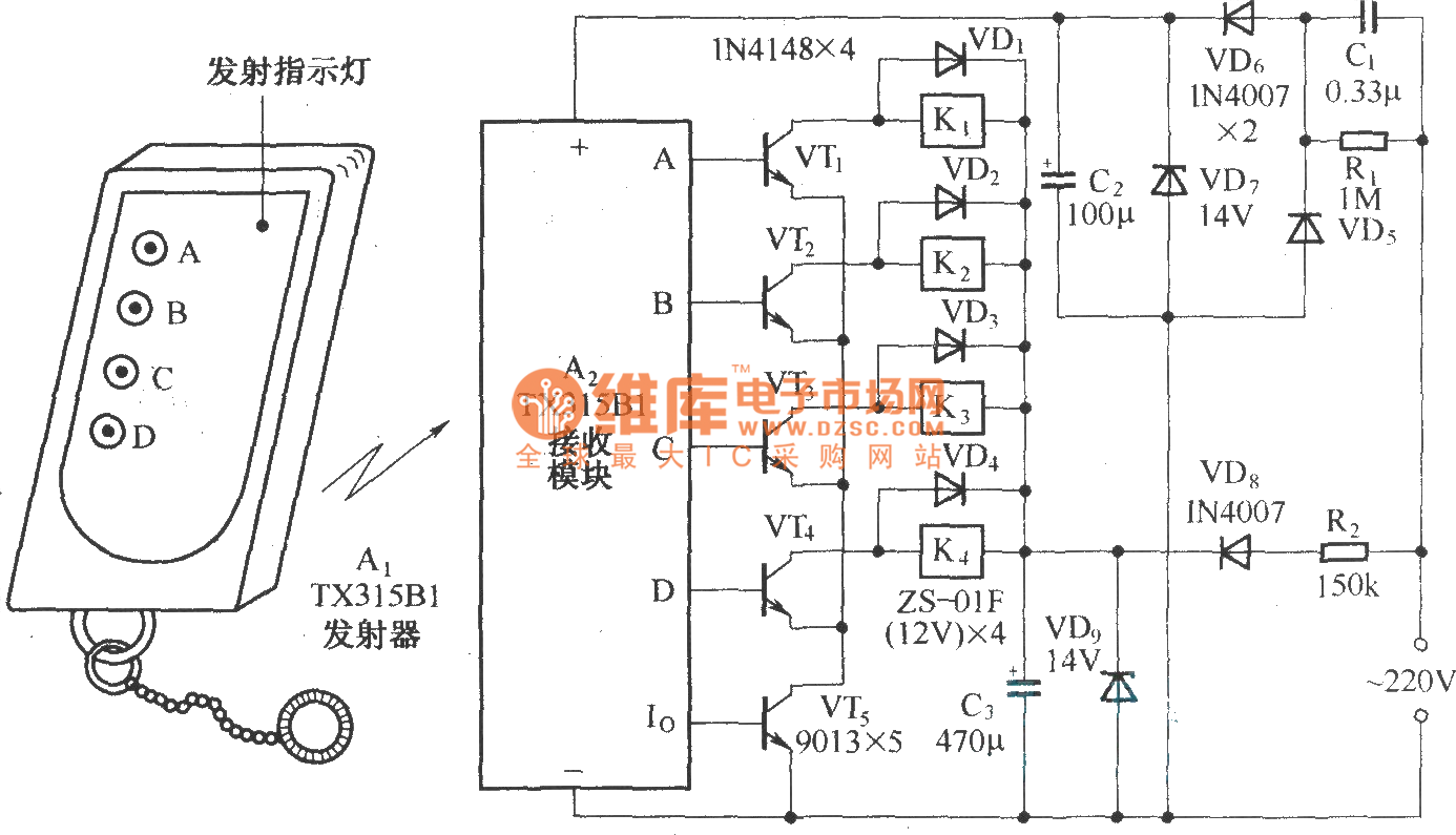
Four way remote control AC switching circuit diagram ...
GE Lighting Control System with 18 RR9P Relays, and an 8 ...

Free Pdf Download » Search Results » Latching Relay Pdf
Just a flip and a relay and on comes the light- Low voltage ...

Kyle Switch Plates: How to Replace a Low Voltage GE Switch ...
LynTec RS-232 Controlled Retrofit Relay Panels
Low Voltage Relays in Lighting Systems Low Voltage relays ...
Lighting & Electrical > Light Control Systems > Light Control ...

Free Pdf Download » Search Results » Latching Relay Pdf

Lighting & Electrical > Light Control Systems > Light Control ...
Lutron low voltage switching
0 Response to "45 ge rr7 relay wiring diagram"
Post a Comment