44 emon dmon wiring diagram
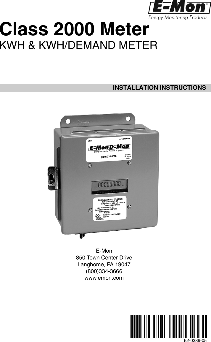
Class 2000 Meter KWH & KWH/DEMAND METER INSTALLATION INSTRUCTIONS E-Mon 850 Town Center Drive Langhome, PA 19047 (800)334-3666 www.emon.
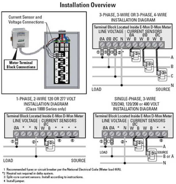
Emon Demon Wiring Diagram 17.01.2019 17.01.2019 7 Comments on Emon Demon Wiring Diagram This E-Mon DMon meter model must be installed indoors, in an area that is free NOTE: Refer to the Wiring Diagrams, for further information on current sensor.
Main Power & Sensor Wiring Diagrams. 11. Section 4.5. Line Voltage/Current Sensor Diagnostics 12. Section 5.0. Monitoring multiple loads with one meter.32 pages

Emon dmon wiring diagram
Jan 17, 2019 · Emon D emon Wiring Diagram. This E-Mon DMon meter model must be installed indoors, in an area that is free NOTE: Refer to the Wiring Diagram s, for further information on current sensor. Main Power and Sensor Wiring Diagram s Section Line Voltage / Current Sensor Diagram s. 13 Device description: Emon Dmon Energy Meter. R.
INSTALLATION INSTRUCTIONS. Class 2000 Meter. KWH & KWH/DEMAND METER. E-Mon. 850 Town Center Drive. Langhome, PA 19047. (800)334-3666 www.emon.com ...
Section 6.4 Current Sensor Installation & Wiring 17 Section 6.5 Main Power & Current Sensor Wiring Diagram 19 Section 6.6 Line Voltage/Current Sensor Diagnostics 20 Section 6.7 RS-485 Wiring 21 Section 6.8 RS-232 Communications 24 Section 6.9 Modem Wiring 26 Section 6.10 Modbus RTU Wiring 29 Section 6.11 BACnet MS/TP Wiring 30
Emon dmon wiring diagram.
® www.emon.com info@emon.com E-Mon D-Mon ... Section 5.4 Main Power and Sensor Wiring Diagrams 12 Section 5.5 Line Voltage / Current Sensor Diagrams 13 Section 5.6 RS 485 Wiring 14 Section 5.7 Modem Wiring 15 Section 6.0 Monitoring Multiple Loads with one Meter 16
MAINS Line Voltage & Current Sensor Wiring. Diagrams. 19. Section 4.6. Installation Overview. 20. Section 5.0. Monitoring Multiple Loads with One Meter.
Section 5.3 Current sensor installation and wiring 11 Section 5.4 Main power & sensor wiring diagrams 13 Section 5.5 Line voltage/current sensor diagnostics 14 Section 5.6 RS-485 wiring 15 Section 5.7 Modem wiring 16
® www.emon.com info@emon.com E-Mon D-Mon ... Wiring Diagrams Section 5.6 Line Voltage/Sensor Diagnostics 13 Section 5.7 RS-485 Communications 15 Section 5.8 RS-232 Communications 17 Section 5.9 Modem Wiring 20 Section 5.10 Modbus Wiring 21 Section 5.11 Ethernet Communications 22 ...
INSTALLATION DIAGRAM 1-PHASE, 2-WIRE 120 or 277 VOLT INSTALLATION DIAGRAM (Class 1000 Series Only) *** * These terminals are not used in Class 1000 installations. LINE VOLTAGE CURRENT SENSORS ∅A ∅B ∅C ∅ W B W B W B A ∅B ∅C N * LOAD SOURCE A B C N 3-PHASE, 3-WIRE OR 3-PHASE, 4-WIRE ...
white wires always land on X2 terminals (see wiring diagram). Install split core or solid core CTs on feeder wires. Observe proper line, load and phase orientation. “H1” or label must face source (line). Step 4 Connect the meter to a low amperage (15A) circuit breaker for meter power and reference voltage. Single pole, two pole or three
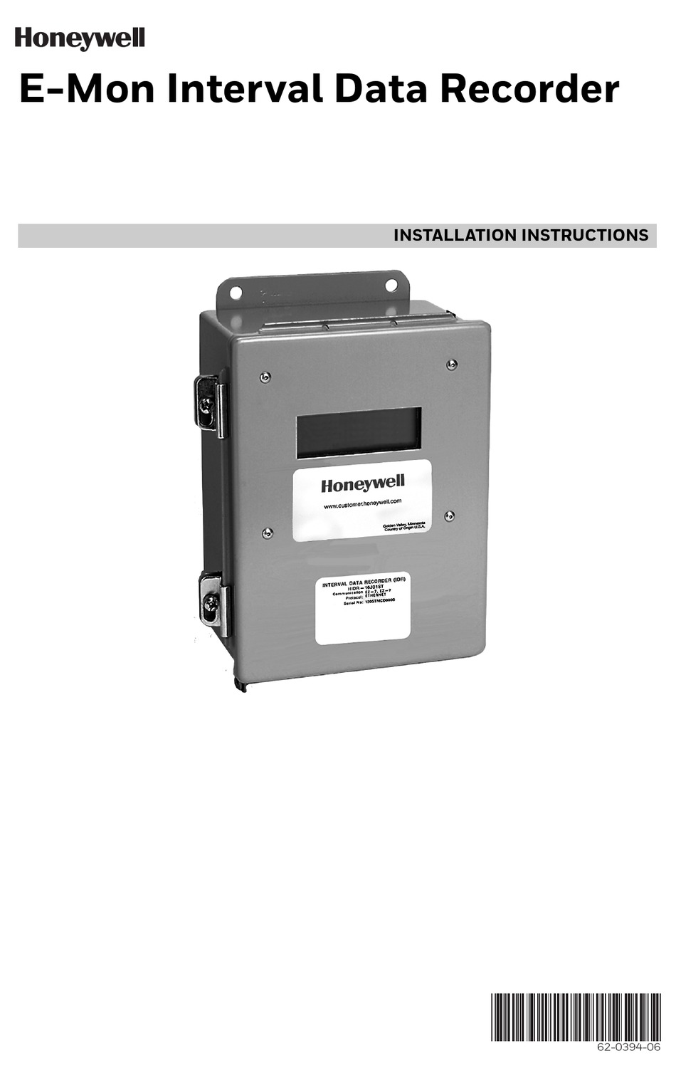
62-0396-03 INSTALLATION INSTRUCTIONS E-Mon Class 2000 Meter KWH & KWH/DEMAND METER 62-0396_C.fm Page 1 Wednesday, May 9, 2018 3:35 PM
www.emon.com info@emon.com . CLASS 3400 METER 62-0391-01 2 ... Section 6.4 Current Sensor Installation & Wiring 14 Section 6.5 Main Power & Current Sensor Wiring Diagram 17 Section 6.6 Line Voltage/Current Sensor Diagnostics 17 Section 6.7 RS-485 Wiring 19
Ekm-omnimeter ii ul v.3 – universal smart meter, single phase or 3-phase, 120 to 240v, 50/60hz, up to 5000 amps













0 Response to "44 emon dmon wiring diagram"
Post a Comment