41 submersible pump installation diagram
Click to watch the most complete set of submersible pump installation ... Baker Water Systems provides well system products outlined in this diagram; ... Diagrams --Typical Pump Installations. The information provided here is for educational purposes only. Technically qualified personnel should install pumps and motors. We recommend that a licensed contractor install all new systems and replace existing pumps and motors. Failure to install in compliance with local and national codes and ...
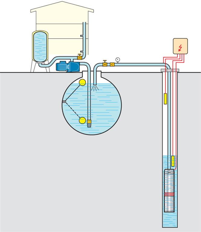
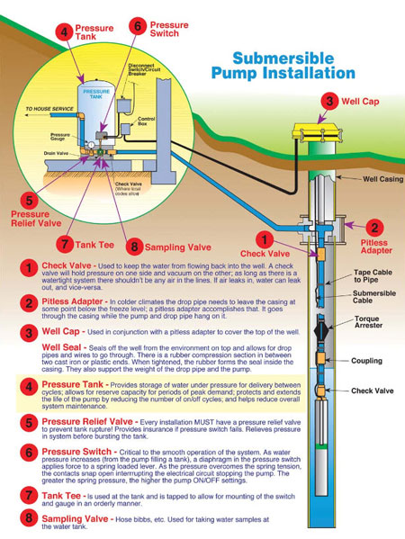
PUMP 3 1. Check Valve Located at the top of the pump to prevent back flow into pump and hold the head of water in the system. 2. Torque Arrestor Installed directly above Submersible Pump to protect pump and well components from starting torque damage. 3. Safety Rope A safety line from the top of the well to the pump. 4. Pitless Adapter
Submersible pump installation diagram
The pump weighs 3 kilograms and allows for fast and easy installation. The device is made of a stainless-steel fastener and inlet that makes it non-corrosive and long-lasting. It has a flow rate of 1.6 gallons per minute for watering. It has a maximum lift of 230 feet and a submersible depth of 100 feet. Product Identifiers Brand… Wiring Diagrams Deep Well Pump Installation 2 Wire Simple 3 - 2 Wire Submersible Well Pump Wiring Diagram. Wiring Diagram includes both examples and step-by-step instructions that might allow you to definitely truly construct your venture. Typical pumps used in a submersible pump installation are either a two or three wire pump. The two wire pumps have the starting capacitor built into the submersible motor whereas the three wire pumps do not have the capacitor built into the motor, they require a control box which is normally found in the pump house at the well head.
Submersible pump installation diagram. INSTALLATION DIAGRAM - SUBMERSIBLE PUMPS ELECTRICAL CONNECTIONS NOT SHOWN ON THIS DIAGRAM PLEASE READ PAGE 1 OF INSTRUCTIONS BEFORE PROCEEDING WITH INSTALLATION.! WARNING HIGH PRESSURE ! For submersible pump applications, install a pressure regulating valve AHEAD of Mascontrol® to reduce pressure to safe levels for the particular application. In this video, I go over the differences of a 2 wire and a 3 wire submersible well pump.This is associated with the starting components for the pump and whet... The wiring connection of submersible pump control box is very simple. 220v 3 wire well pump wiring diagram. Red and yellow might indicate that it is a 2 wire 220 volt pump. 2 wire well pump diagrams are slightly easier to understand and are more straight forward to wire. Electrical ac dc 3 wire 240v for well pump i have a 220v water well pump ... Grundfos Submersible Pump Wiring Diagram Gallery. grundfos submersible pump wiring diagram - A Newbie s Overview of Circuit Diagrams A first appearance at a circuit representation could be complex, however if you can review a subway map, you could read schematics. The objective coincides: obtaining from factor A to direct B. Literally, a circuit is the…
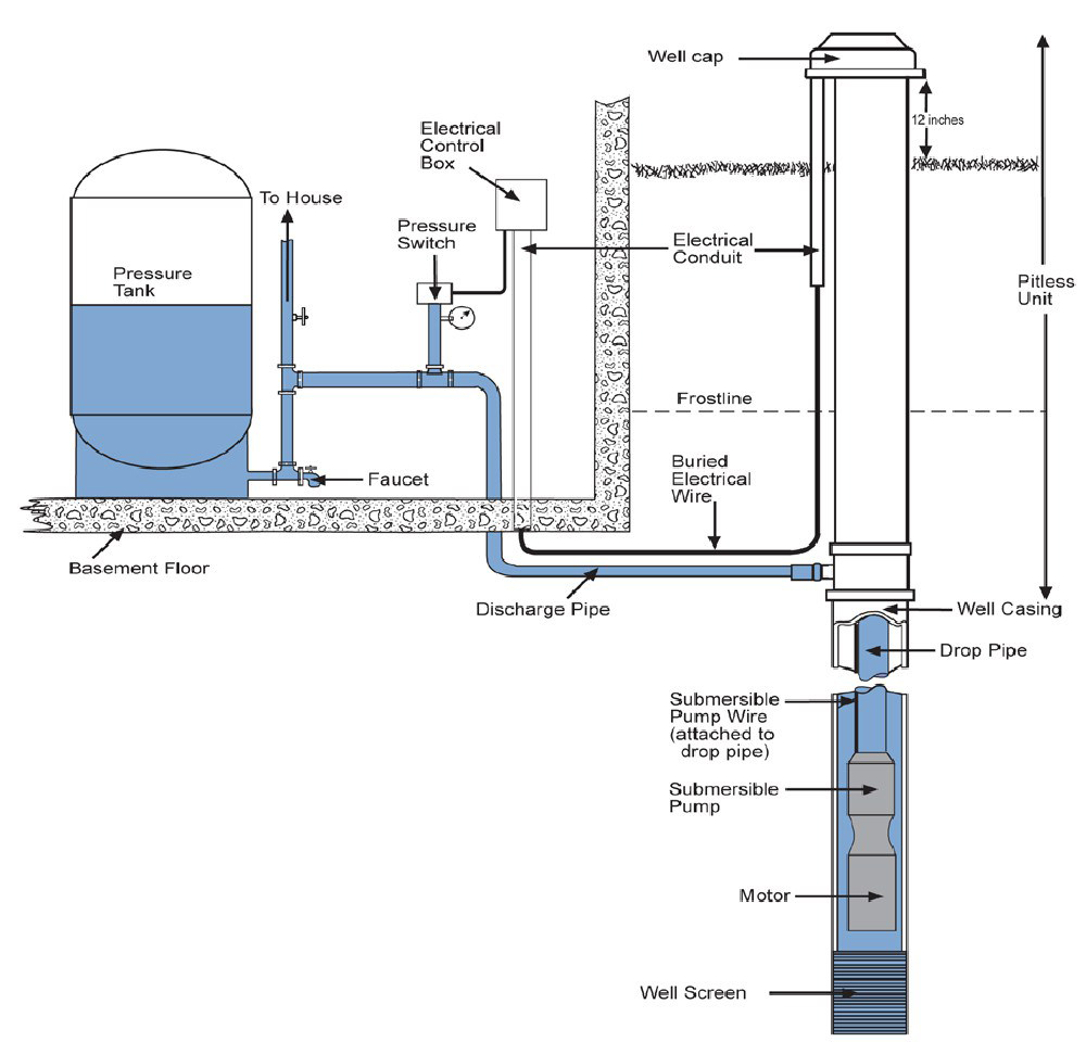
A. WIRING DIAGRAMS A. WIRING DIAGRAMS 22 23 Typical Wiring A Diagrams 3 1 2 5 36 97 3 4 31 42 1 L1 T1 T2 T3 2 L2 3 Start Hand/Off/Auto To Pump Motor Ground Level Control Ground Pressure Switch Lower Upper Electrode To Fused Disconnect Or Circuit Breaker 3Ø Furnas Pumping Panel Line Load Line Load 3 Phase Starter Input Power (As Required By ... Franklin submersible motors are designed primarily for operation in the vertical, shaft-up position. During acceleration, the pump thrust increases as its output head increases. In cases where the pump head stays below its normal operating range during startup and full speed condition, the pump may create upward thrust. Install a Submersible Pump Lesson#4: Follow These Tricks for Lowering a Submersible Pump Using a grinder to remove the sharp burr on the top edge of a steel well casing. Getting pipe and pump and wires into the well in one piece is heavy work, and there are a couple of things you can do to make success more certain. TYPICAL SUBMERSIBLE PUMP INSTALLATION 1. We recommend the captive-air style pressure tank. It has significantly higher drawdown than a standard pressure tank and eliminates water logging problems. The air level in the tank should be 2 lbs. less than pressure switch turn-on level. For a 30-50 switch, this would be 28 lbs. of air with the tank ...
pump which will stand up to the toughest applications. This manual will provide helpful information concerning installation, maintenance, and proper service guidelines. B-2) Receiving: Upon receiving the pump, it should be inspected for damage or shortages. If damage has occurred, fi le a claim immediately with the company that delivered the pump. 3 Phase Water Pump Control Panel Wiring Diagram. angelo. June 19, 2021. 3 Phase Wiring Diagram For House Http Bookingritzcarlton Info 3 Phase Wiring Diagram Fo Electrical Circuit Diagram Electrical Wiring Basic Electrical Wiring. Submersible Pump Control Box Wiring Diagram For 3 Wire Single Phase Submersible Pump Submersible Well Pump Submersible. Submersible Well Pump Accessories Installation Diagram. This illustration is for educational purposes ; It is not intended as an installation guide. Submersible Water Pump Circuit Diagram. Water pump wiring troubleshooting single phase submersible starter motors and controls well installation guide everbilt 1 hp 3 wire motor shurflo 9300 9325 083 automatic level controller for schematic diagram of pv pumping ef sewage pumps welcome. Aim Manual Page 54 Single Phase Motors And Controls Motor ...
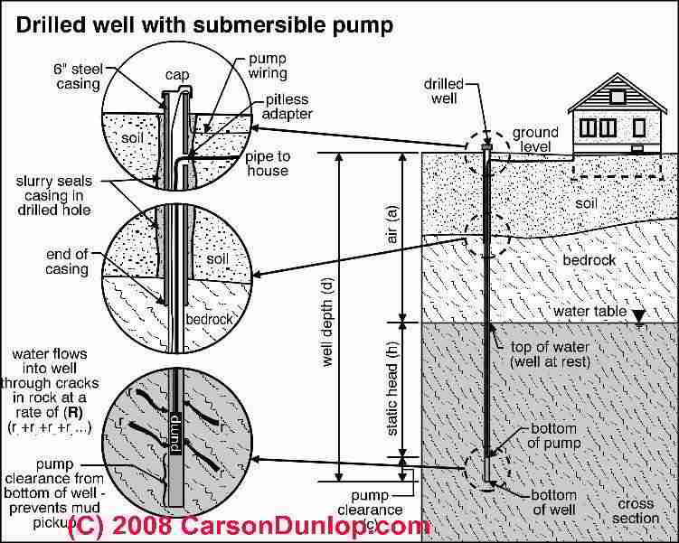
at Pump Discharge Submersible Pump Unit Suction Screen Motor Well Screen or Casing Perforations Note: Keep pump at least 5' from bottom of well and above well screen or casing perforations. FIGURE 1 - Installation Diagram Torque Arrestor

INSTALLATION, OPERATION AND SERVICE MANUAL. LANCASTER 4” SUBMERSIBLE PUMPS. POWERED BY. FRANKLIN 4” SUBMERSIBLE MOTORS. TWO AND THREE WIRE SINGLE AND THREE ...6 pages
Submersible Pump Wiring Diagram Download. Assortment of submersible pump wiring diagram. A wiring diagram is a streamlined standard pictorial depiction of an electric circuit. It shows the components of the circuit as simplified forms, and the power as well as signal connections between the gadgets. A wiring diagram normally provides information regarding the relative setting…

A submersible pump can be either two or three wire, regardless of the voltage coming from the panel, so start at your pump and follow the conduit back. If the conduit runs into a control box before continuing to the water pressure switch, chances are you have a three wire pump. If it runs straight to the pressure switch, it is a two wire.
Single-phase submersible pump control box wiring diagram - 3 wire submersible pump wiring diagram. In the submersible pump control box, we use a capacitor, a resit-able thermal overload, and a DPST switch (double pole single throw). The wiring connection of the submersible pump control box is very simple. Here is the complete guide step by step.

For proper installation in a submersible pump application, you must strip 1/4" of insulation from the wire. The heat shrink tube is then slid over one end, the wires insert into the stakon connector. The heat shrink is then crimped to attach the stakon to the wire. Before you shrink the tube, ensure the tube is centred over the stakon connector.
The Red Jacket submersible turbine pump (STP) is engineered for advanced environmental protection, serviceability, safety, and flow. The Red Jacket STP fits 4-inch NPT threaded, thin-wall risers and is available in a
Please see more wiring amber you can see it in the gallery below. Thanks for visiting our website to search Submersible Pump Control Box Wiring. . Hopefully we provide this is often ideal for you. sy 5317] pump control panel wiring diagram franklin 4 3 wire control box 2 hp 220v 50hz 1ph e herms brewery build forum - skrilnetz 3 4 hp goulds ...
CAUTION: Before operating or installing this pump, read this manual and follow all ... Dynaflo 4” submersible pumps and motors from 1/3 HP through and.12 pages
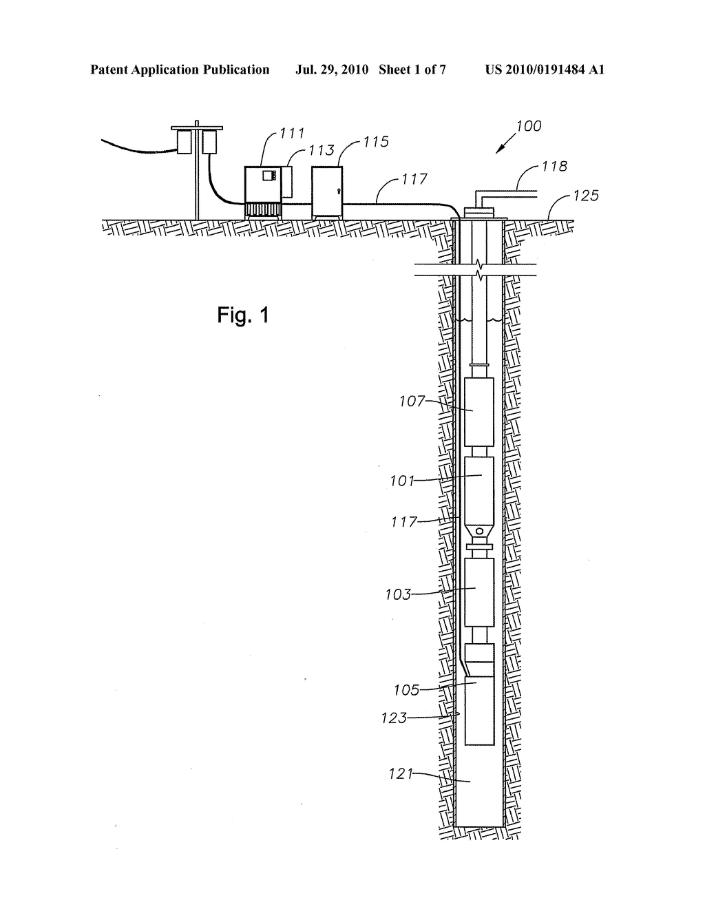
Diagram Submersible Pump Installation Ombu Ukhta03 Ru. Flygt Control Panels. Minicas. Float Switch Installation Wiring Control Diagrams Apg. Puk V1b Single Pump Control Panel 1 230v Or 3 400v Pumps Uk. Float Switch Installation Wiring Control Diagrams Apg. Product Focus September 2020 Onsite Installer. Technoforce Pps Controller Sensorless.
at Pump Discharge Submersible Pump Unit Suction Screen Motor Well Screen or Casing Perforations Note: Keep pump at least 5' from bottom of well and above well screen or casing perforations. FIGURE 1 - Installation Diagram Torque Arrestor
Assortment of submersible well pump wiring diagram. A wiring diagram is a simplified traditional photographic depiction of an electric circuit. It shows the components of the circuit as streamlined forms, and also the power as well as signal connections in between the devices.
Before Installation. Well pump installation can be dangerous when dealing with water and electricity, so extreme caution must be taken. Before getting started, look up your owner's manual and read over the precautions and all other warnings before beginning the installation. The manual will contain important safety precautions, wiring diagrams, tools required for assembly, proper grounding ...

pump can cause an airlock under certain conditions. Incoming 1-phase power 1-phase submersible motor Submersible cable Switch or timer Circuit breaker or fuse disconnect switch FIGURE 2 2-wire, 1-phase, 1/2 through 1-1/2 HP Pump Wiring Diagram CAUTION provide protection against only induced voltage surges on
Typical pumps used in a submersible pump installation are either a two or three wire pump. The two wire pumps have the starting capacitor built into the submersible motor whereas the three wire pumps do not have the capacitor built into the motor, they require a control box which is normally found in the pump house at the well head.

Wiring Diagrams Deep Well Pump Installation 2 Wire Simple 3 - 2 Wire Submersible Well Pump Wiring Diagram. Wiring Diagram includes both examples and step-by-step instructions that might allow you to definitely truly construct your venture.

The pump weighs 3 kilograms and allows for fast and easy installation. The device is made of a stainless-steel fastener and inlet that makes it non-corrosive and long-lasting. It has a flow rate of 1.6 gallons per minute for watering. It has a maximum lift of 230 feet and a submersible depth of 100 feet. Product Identifiers Brand…


0 Response to "41 submersible pump installation diagram"
Post a Comment