41 using the isothermal transformation diagram for an iron–carbon alloy of eutectoid composition
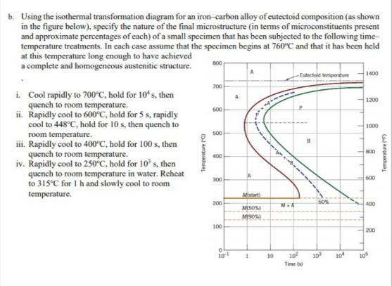
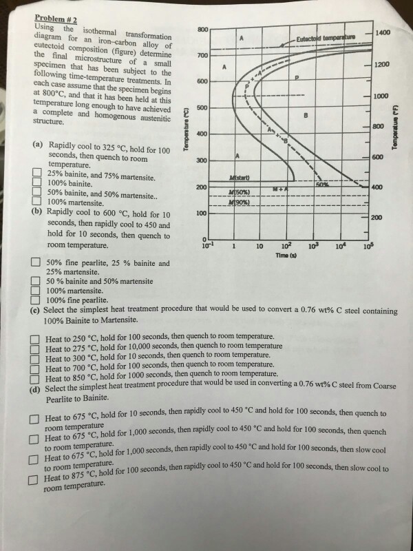
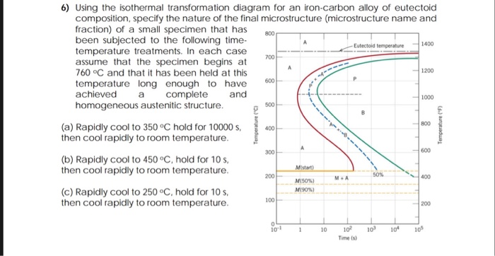
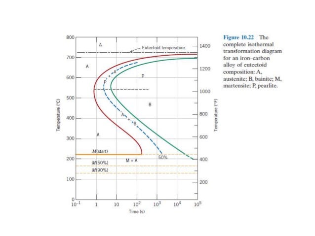
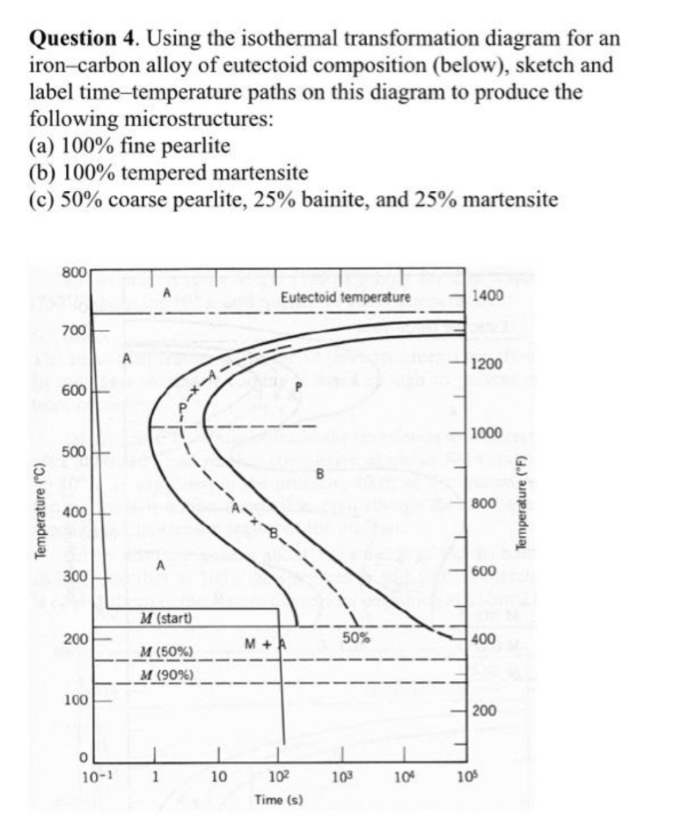
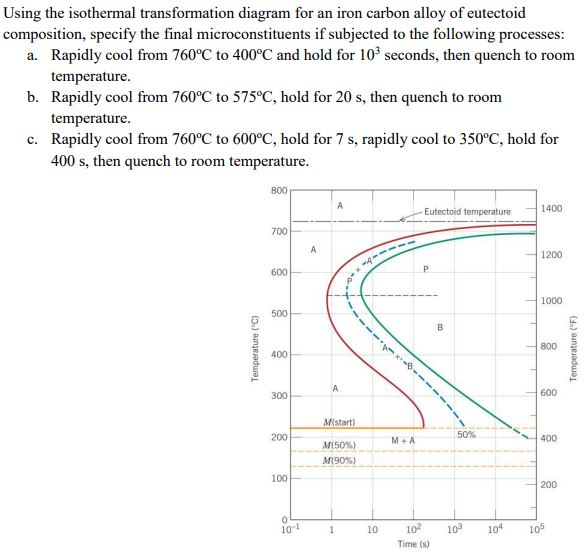
Problem 2 Using the isothermal transformation diagram for an iron-carbon alloy of eutectoid composition (Figure 10.22), specify the nature of the final microstructure (in terms of microconstituents present and approximate percentages of each) of a small specimen that has been subjected to the following time- temperature treatments. Using the Animated Figure 10.22, the isothermal transformation diagram for an alloy of eutectoid composition, specify the nature of the final microstructure (in terms of microconstituents present and approximate percentages of each) of a small specimen that has been subjected to the following temperature treatments.
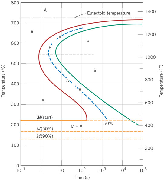
The austenite to pearlite transformation will occur only if the alloy is supercooled to below the eutectoid temperature (727˚C). Time for process to complete depends on the temperature. 15. • Eutectoid iron-carbon alloy; composition, Co = 0.76 wt% C • Begin at T > 727˚C • Rapidly cool to 625˚C and hold isothermally.
Using the isothermal transformation diagram for an iron–carbon alloy of eutectoid composition
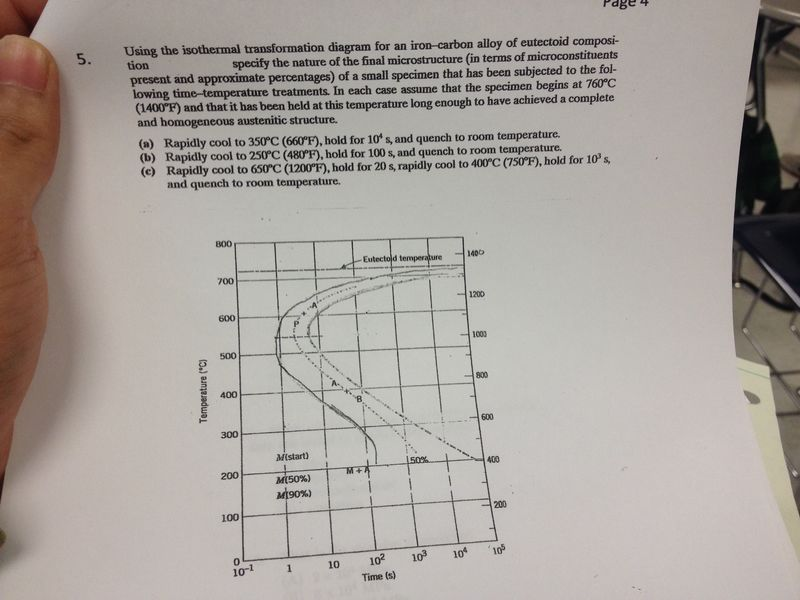
Using the isothermal transformation diagram for an iron-carbon alloy of eutectoid composition (Figure 1), specify the nature of the final microstructure (in terms of microconstituents present and approximate percentages of each) of a small specimen that has been subjected to the following time-temperature treatments. Using the isothermal transformation diagram for an ironcarbon alloy of eutectoid composition figure 1022 specify the nature of the final microstructure in terms of microconstituents present and approximate percentages of each of a small specimen that has been subjected to the following timetemperature treatments. Using the isothermal Transformation Diagram for An Iron-carbon Alloy Of Eutectoid Composition. solved 10 19 using the isothermal transformation diagram 10 19 using the isothermal transformation diagram for an iron carbon alloy of eutectoid position figure 10 22 specify the nature of the final microstructure in terms of microconstituents present and approximate percentages of each of a small ...
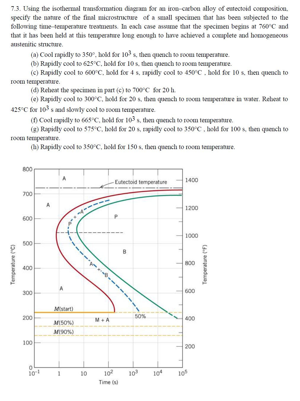
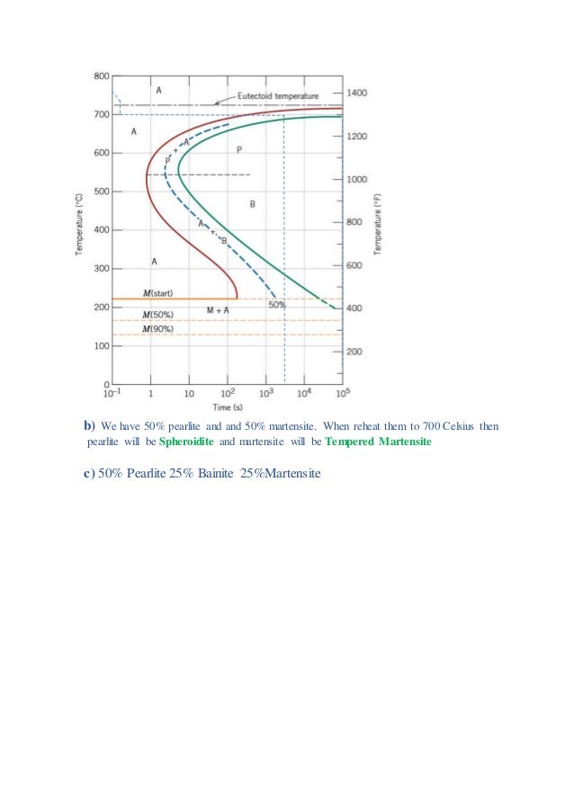
Using the isothermal transformation diagram for an iron–carbon alloy of eutectoid composition. 10.14 This problem asks us to determine the nature of the final microstructure of an iron-carbon alloy of eutectoid composition, that has been subjected to various isothermal heat treatments. Figure 10.14 is used in these determinations. (a) 50% coarse pearlite and 50% martensite (b) 100% spheroidite Using the continuous-cooling transformation diagram for an iron-carbon alloy of eutectoid composition, Figure 10.28, name the microstructural products of specimens having this eutectoid compositions that are first completely transformed to austenite, then cooled to room temperature at the following rates: 175°C/s: 90°C/s: 15°C/s: 2 ... 7.3. Using the isothermal transformation diagram for an iron-carbon alloy of eutectoid composition, specify the nature of the final microstructure of a small specimen that has been subjected to the following time-temperature treatments. In each case assume that the specimen begins at 760°C and that it has been held at this temperature long ... Using the isothermal transformation diagram for an iron-carbon alloy of eutectoid composition (Figure below), specify the nature of the final microstructure (in terms of micro-constituents present and approximate percentages of each) of a small specimen that has been subjected to the following time-temperature treatment: Rapidly cool to 625oC, hold for 10 s, then quench to room temperature.
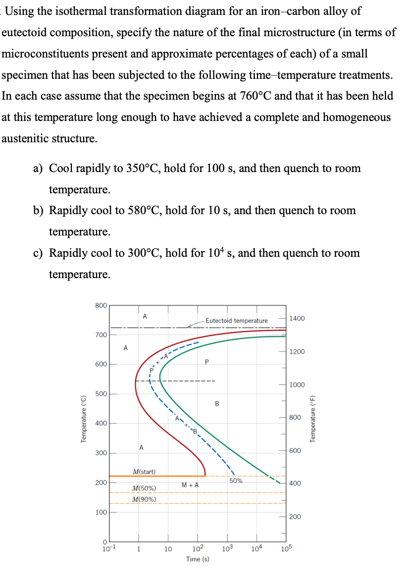
Using the isothermal transformation diagram for an iron-carbon alloy of eutectoid composition, specify the nature of the final microstructure (in terms of microconstituents present and approximate ... In isothermal transformation diagram for an iron-carbon alloy of eutectoid composition, The middle dotted line in the diagram is a representation of 50 % of the composition conversion of the ... Using the isothermal transformation diagram for an iron-carbon alloy of eutectoid composition (Figure), specify the nature of the final microstructure (in terms of micro constituents present and approximate percentages of each) of a small specimen that has been subjected to the following time-temperature treatments. Using the isothermal transformation diagram for an iron-carbon alloy of eutectoid composition, specify the nature of the final microstructure (in terms of microconstituents present and approximate percentages of each) of a small specimen that has been subjected to the following time-temperature treatments.
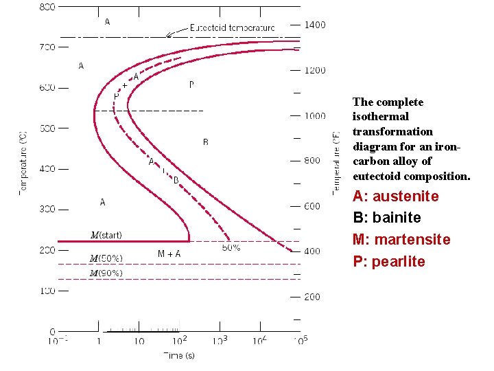
Using the isothermal transformation diagram for an iron-carbon alloy of eutectoid composition, specify the nature of the final microstructure of a small specimen that has been subjected to the ... • Eutectoid composition, C0= 0.76 wt% C • Begin at T > 727°C • Rapidly cool to 625 oC • Hold T (625 oC) constant (isothermal treatment) Fig. 12.14, Callister & Rethwisch 9e. [Adapted from H. Boyer (Editor), Atlas of Isothermal Transformation and Cooling Transformation Diagrams, 1977. Reproduced by permission of ASM 10.18 Using the isothermal transformation diagram for an iron-carbon alloy of eutectoid composition (Figure 10.22), specify the nature of the final microstructure (in terms of microconstituents present and approximate percentages of each) of a small specimen that has been subjected to the following time-temperature treatments. In The complete isothermal transformation diagram for an iron carbon alloy of eutectoid composition. In their simplest form steels are alloys of iron fe and carbon c. Of materials science and engineering 2. 1019 using the isothermal transformation diagram for an iron carbon alloy of eutectoid composition.
Using the Animated Figure 10.22, the isothermal transformation diagram for an alloy of eutectoid composition, specify the nature of the final microstructure (in terms of microconstituents present and approximate percentages of each) of a small specimen that has been subjected to the following temperature treatments.
the iron-carbon alloy system. A sample of the eutectoid composition is cooled from a single-phase region (γ) to a temperature (T) below the eutectoid temperature (T E). The following diagram shows a part of the iron-carbon phase diagram. Concentrations C 1, C 2, C 3, C 4 are various equilibrium ( stable as well as metastable ) concentrations ...
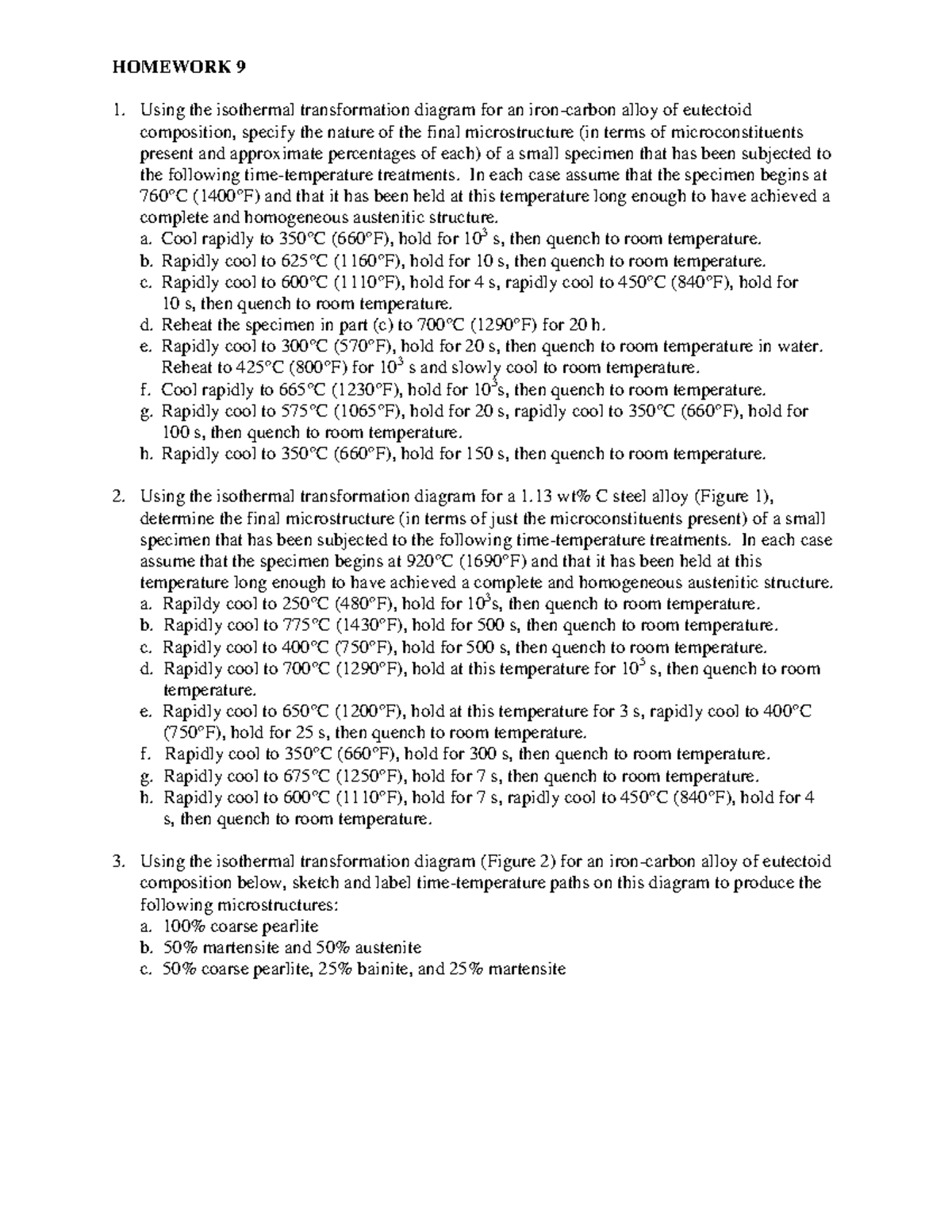
5. Using the isothermal transformation diagram for an iron-carbon alloy of eutectoid composition (Figure 10.23), specify the nature of the final microstructure (in terms of microconstituents presentand approximate percentages of each) of a small specimen that has been subjected to the following time-temperature treatments.

Proeutectoid ferrite can form in steels when the carbon content is lower than the eutectoid composition (hypoeutectoid steels). Likewise, proeutectoid cementite typically forms in steels when the carbon content is greater than that of the eutectoid composition (hypereutectoid steels) (see Fig. 7.1).For plain carbon steels, i.e. Fe-C-based alloys containing about 0.5% Mn and 0.25% Si, 1 the ...
Using the isothermal transformation diagram for an iron-carbon alloy of eutectoid composition (Figure 10.23), specify the nature of the final microstructure (in terms of microconstituents presentand approximate percentages of each) of a small specimen that has been subjected to the following time -temperature treatments. In each case assume ...

Using the supplied isothermal transformation diagram for an iron-carbon alloy of eutectoid composition, specify the nature of the final microstructure (in terms of microconstituents present and approximate percentages of each) of a small specimen that has been subjected to the following time-temperature treatments.
Using the {eq}TTT {/eq} diagram for an iron-carbon alloy of eutectoid composition, predict the final microstructure for different process conditions specified below. For each microstructure, a ...
TTT Diagram For Eutectoid Steel ( Isothermal Transformation Diagram ) Time-Temperature-Transformation (TTT) diagram or S-curve refers to only one steel of a particular composition at a time, which applies to all carbon steels. This diagram is also called as C-curve isothermal (decomposition of austenite) diagram and Bain's curve.
Using the isothermal Transformation Diagram for An Iron-carbon Alloy Of Eutectoid Composition. solved 10 19 using the isothermal transformation diagram 10 19 using the isothermal transformation diagram for an iron carbon alloy of eutectoid position figure 10 22 specify the nature of the final microstructure in terms of microconstituents present and approximate percentages of each of a small ...
Using the isothermal transformation diagram for an ironcarbon alloy of eutectoid composition figure 1022 specify the nature of the final microstructure in terms of microconstituents present and approximate percentages of each of a small specimen that has been subjected to the following timetemperature treatments.
Using the isothermal transformation diagram for an iron-carbon alloy of eutectoid composition (Figure 1), specify the nature of the final microstructure (in terms of microconstituents present and approximate percentages of each) of a small specimen that has been subjected to the following time-temperature treatments.


.PNG)


0 Response to "41 using the isothermal transformation diagram for an iron–carbon alloy of eutectoid composition"
Post a Comment