45 mercruiser trim solenoid wiring diagram
photokrattphie-baby.de Mercury outboard wiring diagrams 115 efi engine wire harness 150 service manual pdf mariner 40 hp motor diagram 1977 1989 mercruiser power trim schematic starter solenoid ocean pro gear 1985 black max what is the for a 1983 2018 150hp repair evinrude tachometer leenzuthouse 2x new cdi switch box 90 untitled issues any help pls 1996 force bys Mercury 40 50 60 Hp … Mercruiser Trim Position Sender Wiring Diagram - Diagram ... Related with mercruiser trim gauge wiring. Download mercruiser trim sender wiring diagram for free. If installing on boat that is equipped with merruiser stern drive, rown/white wire is connected to trim sender terminal block. With the drive in the full down position you will install the switches being careful not to misalign.
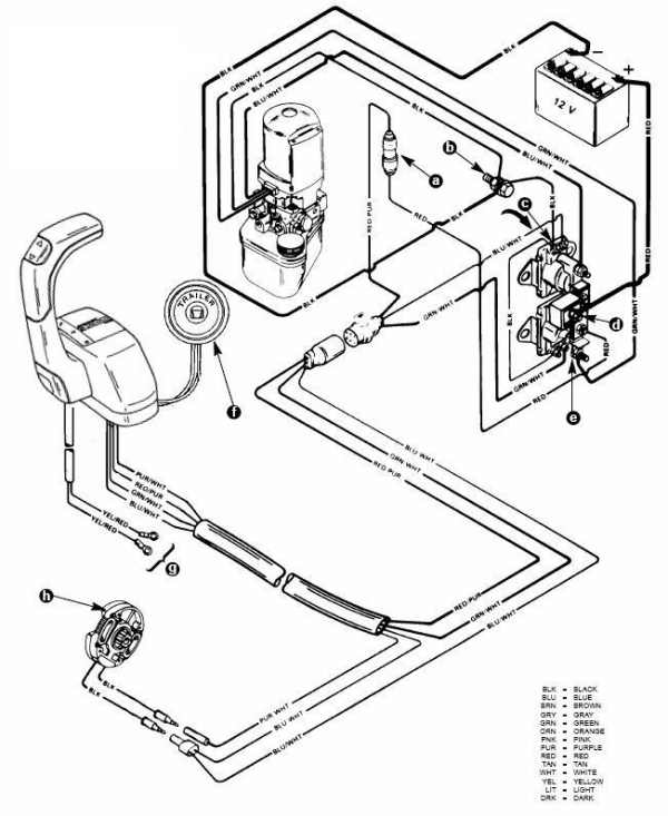
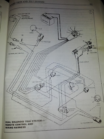
Mercruiser Power Trim Solenoid Wiring Diagram Trim System Wiring Diagrams. 6 - 10 Power Trim Hydraulic Schematic. 6 - 13 .. c - "UP" Solenoid d - Amp Fuse. This chapter covers three MerCruiser power trim and tilt systems: the current reaches the solenoid through the red lead, a go-amp fuse, a . Reconnect wires to back of new switch/sender. . Figure 2 is a functional diagram of the hydraulic.

Mercruiser trim solenoid wiring diagram
PDF Mercruiser 30l Engine Diagram 5 7 Mercruiser Engine Wiring Diagram Library. Omc Trim Gauge Wiring Diagram. 1997 mercruiser 5 7 starter wiring page 7l v8 draco topaz 1996 4 3 diagram 1 0 mpi when i turn key solenoid boat in my 3l v6 engine b19f0 merc 502 efi 0l marine schematic faint switch on. Mercruiser Starter Solenoid Wiring Diagram - Wiring Diagram Wiring Diagram for motor trim solenoid | Boating Forum ... Re: Wiring Diagram for motor trim solenoid Red/purple is usually fused +12VDC. It should be connected from a source of power, to the trim switch. The trim switch will then send the power (when activated by your thumb) to the green (trim down) or Blue (trim up) wire on the trim pump. Outstanding Mercruiser Trim Solenoid Wiring Diagram Atwood ... Mercruiser power trim solenoid wiring diagram. Each component ought to be placed and connected with different parts in particular way. Higginbotham sender wiring diagram mercruiser trim sender wiring diagram 2007 4 3 mercruiser wireing diagram 4 3 mpi engine. A 3 button power trim panel control operates the a dual solenoid trim pump is ...
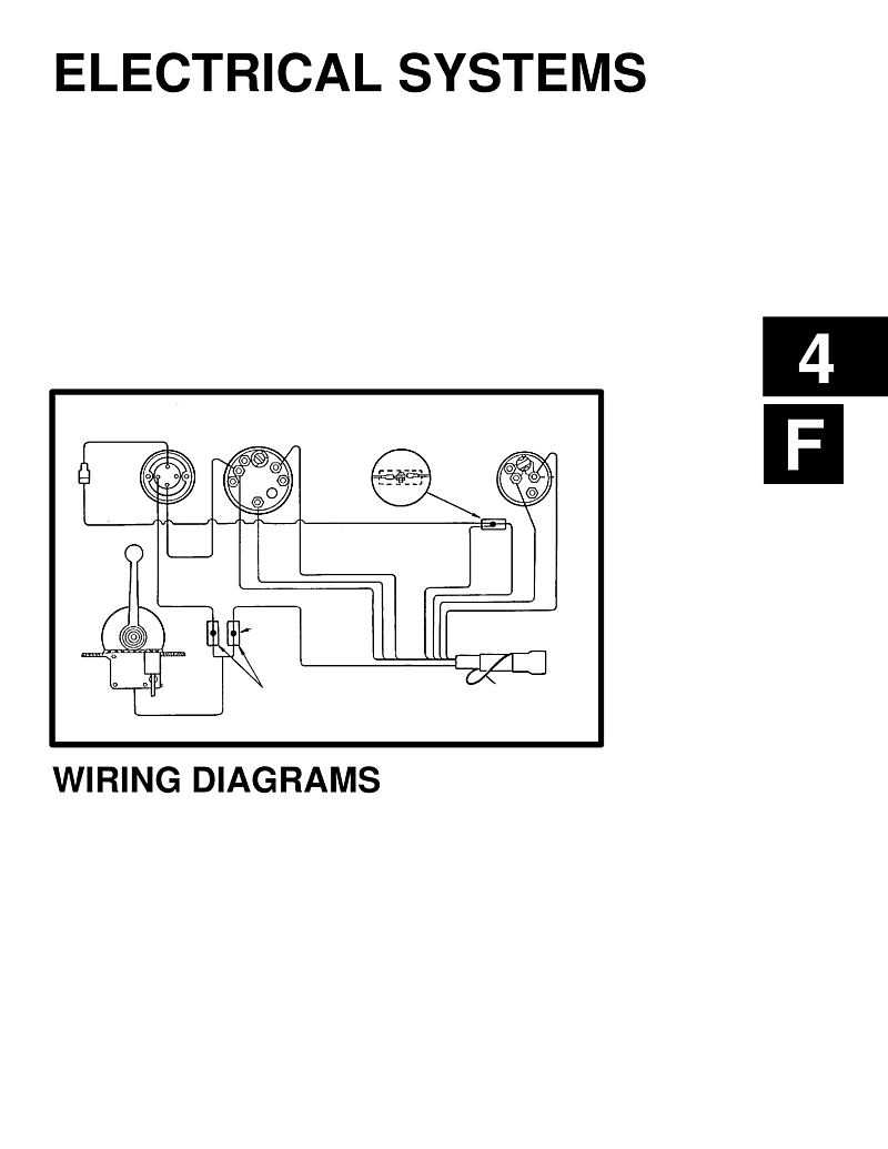
Mercruiser trim solenoid wiring diagram. Mercruiser tilt trim NOT WORKING Fix and testing the pump ... Mercruiser tilt and trim repair. How to test your tilt and trim pump. Mercruiser tilt and trim problems. Hot to fix your tilt and trim. Mercruiser Oildyne Trim Pump Wiring Diagram Mercruiser Trim Pump Wiring Diagram ~ here you are at our site, this is images about mercruiser trim pump wiring diagram posted by Maria Rodriquez in Mercruiser category on Nov 22, You can also find other images like wiring diagram, parts diagram, replacement parts, electrical diagram, repair manuals, engine diagram, engine scheme, wiring. PDF Power Trim and Tilt Systems - West Virginia University The MerCruiser power trim system permits ... A dual solenoid trim pump is generally usedIn each system, a bi-metal switch built into the when an in-handle trim control is required or whenbrush lead protects the pump motor from ... Figure 2 is a functional diagram of the hydraulic PDF ELECTRICAL SYSTEMS - mercruiser-shop.at 90-806535940 893 WIRING DIAGRAMS - 4D-1 Wiring Colors for MerCruiser BIA Color Code Where Used Black All Grounds Brown Reference Electrode-MerCathode Orange Anode Electrode-MerCathode Lt. Blue/White Trim- "Up" Switch Gray Tachometer Signal Green/White Trim -"Down" Switch Tan Water Temperature Sender to Gauge Lt. Blue Oil Pressure Sender ...
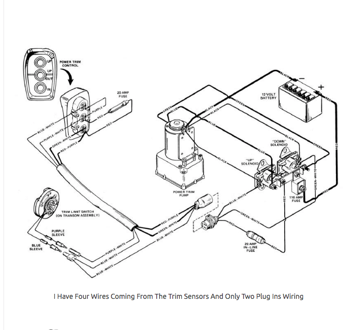
Mercury Outboard Trim Wiring Diagram - justussocializing.org Mercury Outboard Trim Wiring Diagram - One of the most difficult automotive fix tasks that a mechanic or repair shop can understand is the wiring, or rewiring of a car's electrical system.The misfortune in point of fact is that every car is different. afterward maddening to remove, replace or fix the wiring in an automobile, having an accurate and detailed mercury outboard trim wiring ... PDF Electrical Systems If installing on boat that is equipped with MerCruiser Stern Drive, BROWN/WHITE wire is connected to the trim sender terminal block. Also can be used for an accessory (limit 5 amps). NOTE 2: An accessory fuse panel may be connected at this location. The combined current draw of the primary station and secondary station MUST NOT exceed 5 amps. Mercruiser Alpha Dual Power Trim | YBW Forum The blue/white wire goes via the trim limit switch so only works on 'UP' There should be a 3rd wire Purple/white from the trim buttons which goes direct to the Up relay so when the trim limit is reached you can then drive the trim up all the way for trailoring. Mercruiser Trim Solenoid Wiring Diagram For Your Needs Mercruiser Trim Solenoid Wiring Diagram Source: forums.iboats.com READ Battery Isolator Wiring Diagram Manufacturers Database Read wiring diagrams from unfavorable to positive in addition to redraw the routine as a straight collection.
Wiring Diagram For Boat Trim - Wiring Diagram Line common outboard motor trim and tilt mercruiser power wiring schematic wire diagram 212 pump rinker boat 1981 with troubleshooting drive trims down but tabs rocker switch carling basic electricity your leveler tab works only when harness fp marine bennett add to 1998 yamaha tech insta levelers throttle handle club sea ray 881170a15 side mount … Mercruiser I/O Trim not working - BASS BARN When you push the trim up or trailer button you should read ohms between the red/purple and blue/white wire pins. Down button pushed you should read ohms between the red/purple and green/white wire pins If you go to the same connector on the trim unit side you should get voltage coming from the red/purple pin to a known ground. Mercruiser Trim Pump Wiring Diagram - IOT Wiring Diagram mercruiser power trim wiring schematic mercury pump diagram is sender the troubleshooting sterndrive and 898r from 1983 up throttle handle switch club sea ray hydraulic control panel cables connected maxum boat 2 wire motor drive trims down but assembly 14336 series bracket stainless steel reverse interlock boating 3 0l won t go common outboard … Mercruiser Power Trim Wiring Diagram - Free Wiring Diagram ... Mercruiser power trim solenoid wiring diagram. According to earlier, the traces at a mercruiser trim sender wiring diagram signifies wires. Source: hanenhuusholli.blogspot.com. Figure 1 shows a typical system. Viewing a thread 2 wire motor trim wiring diagram. Source: 2020cadillac.com
Jeff Henke (jkhenke77) - Profile | Pinterest
Wiring Diagram For 3 Button Single Solenoid Trim Pump For ... description: schematron.org for ower-trim-pump motor but operate two solenoids which operate the motor remotely using larger wires with the same blue and green colors.Oct 25, · To test the motor itself, bypassing the relays and relay wiring, find the two heavy gauge wires that lead to the trim/tilt pump motor.
Bayliner capri starter problems - The Hull Truth - Boating ...
Outstanding Warn Winch Wiring Diagram 2 Solenoid Two ... Wiring diagram contains the two examples and step by step directions that will permit you to definitely truly build your venture. Otherwise the structure won t work as it should be. Warn winch wiring diagram 4 solenoid warn winch wiring diagram 4 solenoid every electrical arrangement is composed of various diverse pieces.
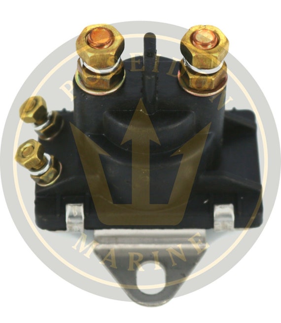
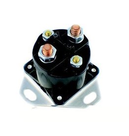
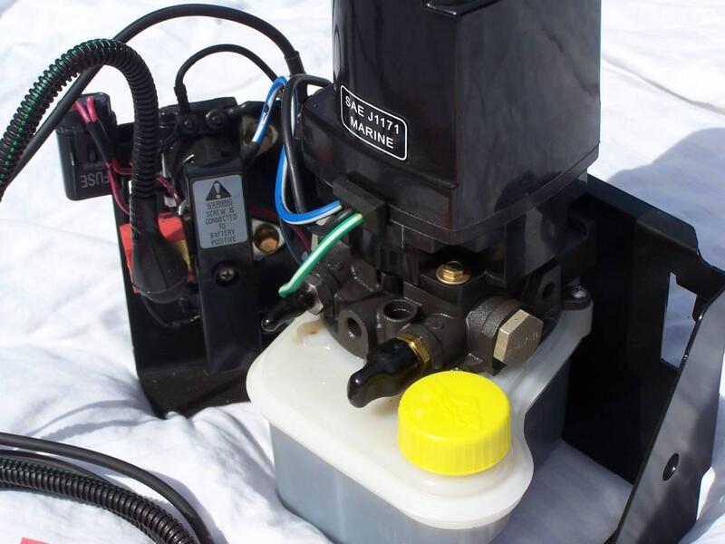
Power Trim/Starter Solenoid for MerCruiser RO: 89-96158T 18-5817
Favorite Mercruiser Trim Wiring Diagram 3 Wire Motor ... Impressive Mercruiser Trim Wiring Diagram Simocode Pro V Mercruiser 4 3 Wiring Diagram Luxury Cute Mercruiser Trim Sender Ford Ranger 2004 Ford Ranger 2005 Ford Ranger Look on the back of the gauge and see if there is a br w wire there. A wiring diagram is a simplified traditional photographic depiction of an electrical circuit.
CHRYSLER FORCE OUTBOARD TRIM MOTORS, SOLENOIDS, RELAYS ...
Wiring Diagram For 3 Button Single Solenoid Trim Pump For ... Wiring Diagram For 3 Button Single Solenoid Trim Pump For Mercruiser My outdrive is all up (out) hydraulic pump runs. Nothing Lastly, you'd be best advised to pick up a manual for this drive/engine package. This MerCruiser power trim and tilt system is electro- Single or dual solenoids may be used according to system application.
continuousWave: Whaler: Reference: Ignition Switch
How to Replace A Mercruiser Solenoid / 4.3 Mercruiser ... How to replace your 4.3 Mercruiser Solenoid. Where do the wires go? The part cost me $28 at an Auto Parts store. Starter Slave Solenoid. Clicking. Part numbe...

install electronic ignition kit in a Mercruiser 120 engine?
PDF Mercruiser Service Manual Starter Solenoid Wiring Diagram ... Find the cheap Mercruiser Trim Solenoid Wiring Diagram, Find the best Mercruiser Power Trim Hose (Port Side) for the R, MR, Alpha One and Alpha One Gen.Lookup MerCruiser (4 bbl.) gm v-8 engine & stern drive by component and buy discount parts from our large online inventory. View and
Mercruiser tilt/trim stopped working | YBW Forum
MERCURY 150 EFI SERVICE MANUAL Pdf Download | ManualsLib View and Download Mercury 150 EFI service manual online. Electronic Fuel Injection,. 150 EFI engine pdf manual download. Also for: 175 efi, 200 efi, 150xri, 175xri, 200xri, 0t409000.

Starter Solenoid Relay Mercury Marine 89-817109A2 67-730
Installation Drawings - Filter | Mercury Marine TDI 4.2L V-8 Sterndrive 2013-2017. 383 MAG Bravo 4V Installation Drawing 2013-2014. 8.1L Horizon V-Drive Installation Drawing 2013-2014. 2.0L Sterndrive 2014-2017. TDI 3.0L V-6 Inboard 45 Trans No Angle 2014-2017. TDI 3.0L V-6 Inboard 63 Trans No Angle 2014-2017. 540 MAG Bravo 4V Installation Drawing 2014-2014.

Wiring diagram for 3.0 mercruiser | Boating Forum - iboats ...
Mercruiser Power Trim Solenoid Wiring Diagram Mercruiser Power Trim Solenoid Wiring Diagram The two on the left are trim, and the two on the right are tilt. controller and a three wire plug on the pump motor, as well as power and ground. I've searched everywhere for a wiring diagram and haven't had any luck yet. two solenoids which operate the motor remotely using larger wires with the same.

Bracket Installation Instructions - Porta Products Corporation
Mercruiser Trim Pump Wiring Diagram - Wiring Diagram Line mercruiser power trim wiring schematic mercury pump diagram is sender the troubleshooting sterndrive and 898r from 1983 up throttle handle switch club sea ray hydraulic control panel cables connected maxum boat 2 wire motor drive trims down but assembly 14336 series bracket stainless steel reverse interlock boating 3 0l won t go common outboard …

Buy Outboard Engine 89-825096T 825096T01 Starter Solenoid ...
PDF Mercruiser Trim Sender Wiring Diagram drive trims down but not up marine. mercruiser trim sender limit switches amp wiring diagram. the best boat forum for answers to hard qustions about boats. boatinfo mercruiser service manual nr 5 1978 1993. amazon com new starter solenoid fits mercury marine 65 75 MERCRUISER GM4 SERVICE MANUAL Pdf Download

Boat Repair Forum - Marine Tilt Trim Motor Tech Tips
PDF Engine-mercruiser 60 576 WIRING DIAGRAMS ENGINE-MERCRUISER 228=TR, ?SS=TR (SERIAL NO. 4175500 AND UP), 2809TRS, 330-TR AND 33O=TRS ALTERNATOR STARTER MOTOR NEUTRAL 12-VOLT SAFETY BATTERY WITCH Y WATER TEMPERATURE 8 OIL PRESSURE SENDER Aa DISTRIBUTOR ELECTRIC SHIFT J To +I2 Stud NEUTRAL . Ormga FORWARD. Gmm REVERSE -Slum

Trim pump | Club Sea Ray
Outstanding Mercruiser Trim Solenoid Wiring Diagram Atwood ... Mercruiser power trim solenoid wiring diagram. Each component ought to be placed and connected with different parts in particular way. Higginbotham sender wiring diagram mercruiser trim sender wiring diagram 2007 4 3 mercruiser wireing diagram 4 3 mpi engine. A 3 button power trim panel control operates the a dual solenoid trim pump is ...

Feather Craft - Hookup - Wiring / Cables / etc...
Wiring Diagram for motor trim solenoid | Boating Forum ... Re: Wiring Diagram for motor trim solenoid Red/purple is usually fused +12VDC. It should be connected from a source of power, to the trim switch. The trim switch will then send the power (when activated by your thumb) to the green (trim down) or Blue (trim up) wire on the trim pump.
12 Volt NEW Power Tilt Trim Relay for Mercury and Mercruiser ...
PDF Mercruiser 30l Engine Diagram 5 7 Mercruiser Engine Wiring Diagram Library. Omc Trim Gauge Wiring Diagram. 1997 mercruiser 5 7 starter wiring page 7l v8 draco topaz 1996 4 3 diagram 1 0 mpi when i turn key solenoid boat in my 3l v6 engine b19f0 merc 502 efi 0l marine schematic faint switch on. Mercruiser Starter Solenoid Wiring Diagram - Wiring Diagram

Throttle handle trim switch | Club Sea Ray

New WSM Outboard Trim Solenoid "A" UP [OEM #38410-94552]
Mercruiser Trim Pump - Troubleshooting Help - The Hull Truth ...
Mercruiser Power Trim Wiring Schematic | PerfProTech.com

Key Switch Wire Diagram for A Mercury Outboaed with Chock ...

www.iFourWinns.com • View topic - Engine will not start

I have a 1981 outboard with power trim and tilt. When you ...

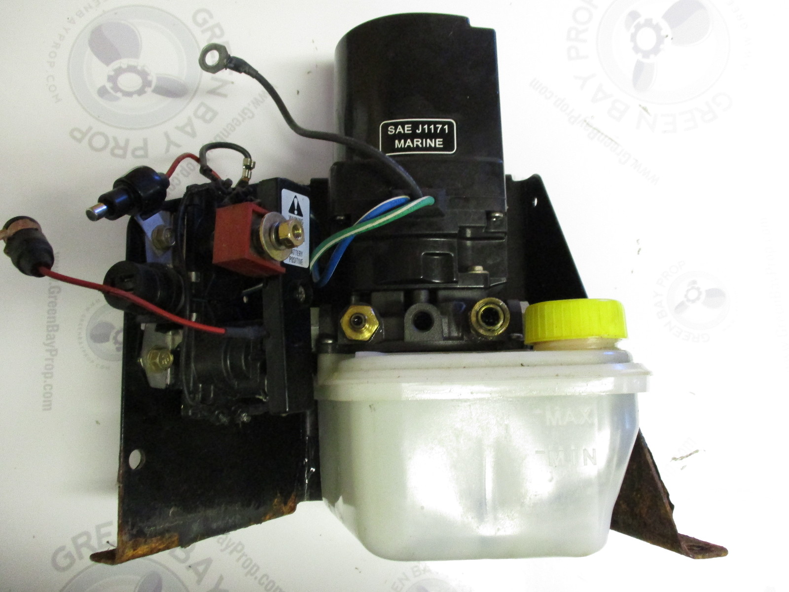
MerCruiser Stainless Steel Trim Pump Bracket W/Wiring ...

I HAVE A 1996 MERCURY FORCE OUTBOARD, 40 HP PURCHASE A ...
14336A8 Trim & Tilt Motor w/Solenoid Bracket for Mercruiser ...
tilt/trim limit & gauge wiring - The Hull Truth - Boating and ...
New Mercury/Mercruiser Trim Pump | Free Classifieds- Buy ...

MaySpare 12V Power Trim Solenoid Switch For Mercury Mariner Outboard Motors 35-275 HP 89-846070 89-94318 MerCruiser 89-96158T

How to fix trim solenoid Part 1 Removal - YouTube
FiberGlassics® - Tilt/Trim Troubleshooting - FiberGlassics ...

MerCruiser Stainless Steel Trim Pump Bracket W/Wiring ...

Question is: What colors are the wires to the "up" trim ...
Mercruiser Electrical Diagrams Engines, Drives And ...
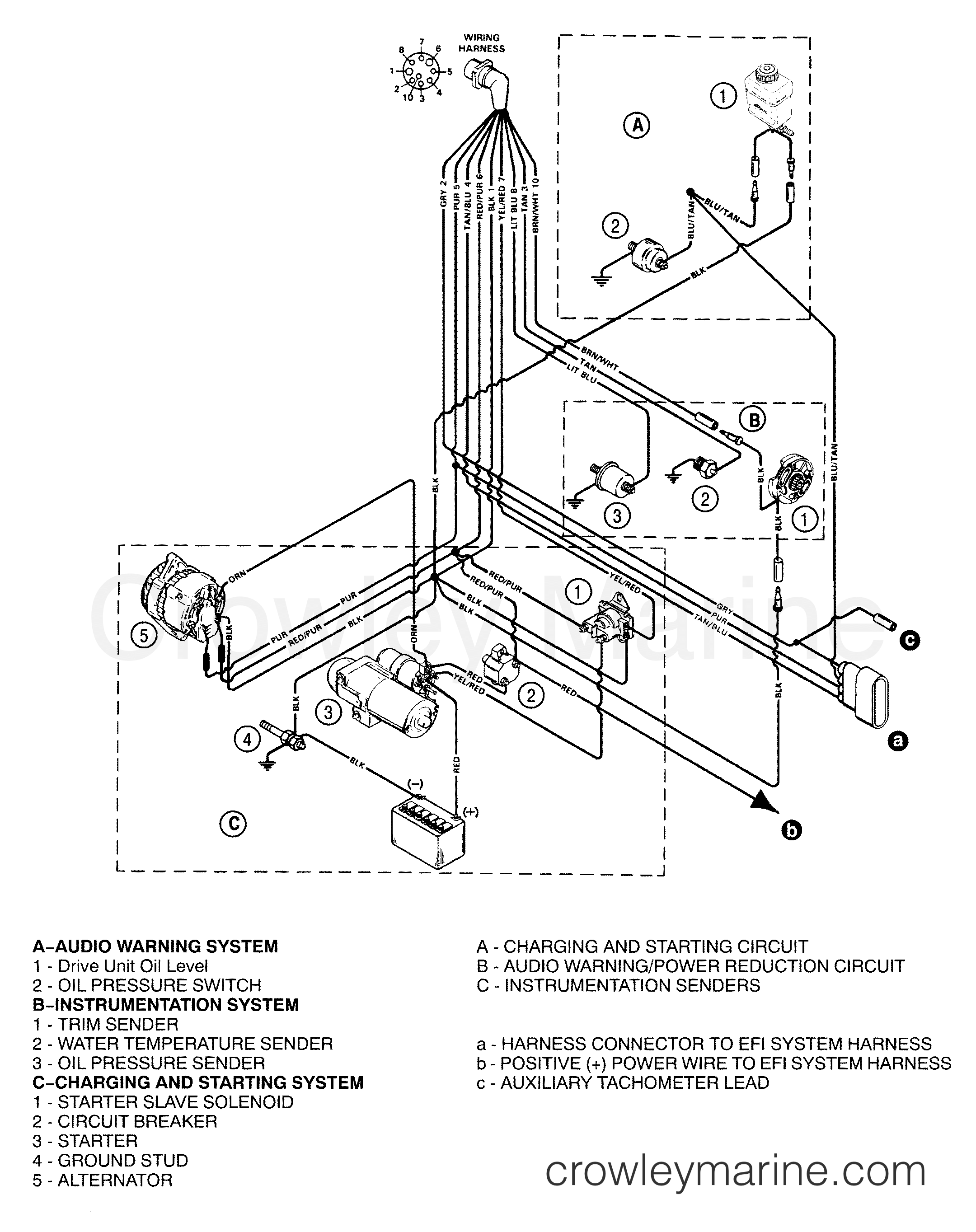
WIRING HARNESS (ENGINE) - 1996 Stern Drive 5.7L TBI [ALPHA ...

Amazon.com: MaySpare 12V Power Trim Solenoid Switch For ...

Rareelectrical NEW TILT TRIM ASSEMBLY COMPATIBLE WITH MERCURY MARINE FLOOR MOUNT 88183A5 14336A9 14336A8

Troubleshooting, Testing and Bypassing SPDT Power Trim Tilt ...
Common Outboard Motor Trim and Tilt System Wiring Diagrams ...

12V Starter/Power Trim Solenoid for Mercury Mariner Outboard ...
mercruiser trim sender wiring - The Hull Truth - Boating and ...

Adding a remote trim adjustment switch for outboards ...
MerCruiser Bravo One Trim Pump Assembly (Complete) Parts
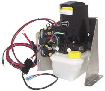
![Bracket Trim Pump Stainless Steel Mercruiser Oildyne Prewired 862548A 1 [PH200-T066-K] - $139.95 : ebasicpower.com, Marine Engine Parts | Fishing ...](https://bpi.ebasicpower.com/mm5/graphics/00000001/PH200-T066-K.jpg)
Bracket Trim Pump Stainless Steel Mercruiser Oildyne Prewired 862548A 1 [PH200-T066-K] - $139.95 : ebasicpower.com, Marine Engine Parts | Fishing ...
![Electrical [Wiring Diagram (Pro 50F)] [1989] | Crowley Marine](https://cdn.crowleymarine.com/docs/8696/62c9ea60-7e1e-11ea-9ae0-21d59233e7c7-lg.jpg)
Electrical [Wiring Diagram (Pro 50F)] [1989] | Crowley Marine
![WIRING HARNESS - 1998 Stern Drive 3.0L [ALPHA] 4111021L1 ...](https://cdn.crowleymarine.com/mercury/uFkoyUGg.png)
WIRING HARNESS - 1998 Stern Drive 3.0L [ALPHA] 4111021L1 ...
0 Response to "45 mercruiser trim solenoid wiring diagram"
Post a Comment