42 furnace air flow diagram
› heat-pumpHeat Pump Thermostat Wiring Diagram - Air Conditioning Systems Heat pump thermostat wiring - A typical wire color and terminal diagram. As shown in the diagram, you will need to power up the thermostat and the 24V AC power is connected to the R and C terminals. PDF Multi-position Furnace Sufficient air must be provided to ensure there will not be a negative pressure in furnace room or Also, see Furnace Wiring Diagram in Figure 22. Install proper electrical grounding by attaching NOTE: For natural gas, if gas flow rate can't be properly set within these pressure ranges then you...
centralboiler.com › pdf › systemdiagramsDefinitions - Best Outdoor Wood Furnace | Central Boiler Forced Air Furnace For illustration purposes only, water heater styles may vary. NOTE A pump must be installed in the hot supply line between the outdoor furnace and thermostatic valve. Outdoor furnace water temperature setpoint should be set at 185˚F (85˚C) minimum. NOTE On multi-speed fans, cap and tape off any extra wires. NOTE

Furnace air flow diagram
PDF Entropy-temperature and transmission diagrams for air V. the AIR flow diagram. VI. Maximum power transmitted through pipes. Entropy-temperature and transmission diagrams for AIR. I. introduction. 1. Preliminary.-In engineering calculations graphical methods not infrequently afford a satisfactory... Trane Replacement Furnace Filters | By Model | FurnaceCompare® 17-04-2020 · If your unit is an upflow model then the air filter is found in the bottom and side of the furnace cabinet. If the unit is a downflow model, then the filter is found somewhere in the duct work. For replacement filters see the chart below, which is based on the air flow configuration and cabinet width. Furnace Filters for the Trane XL90 TEC ALT Process Descriptions and Flow Diagrams | PDF The following are brief descriptions and pictorial Process Flow Diagrams of Selected Ironmaking Processes: 3-2.1 shaft furnace processes The heated air burns the injected fuel and most of the coke charged in from the top to produce the heat required by the process and to provide...
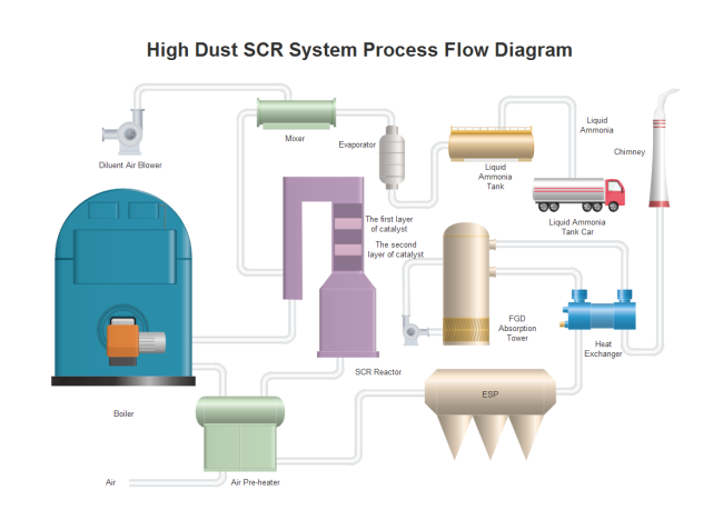
Furnace air flow diagram. furnace air flow chart - Gfecc Furnace Air Flow Diagram Wiring Schematic Diagram 10. Air Direction Flow In Furnace Furnace Installation. Furnace Air Flow Chart Unique Block Diagram Flow Chart Of. Hvac Diagram Standard Heating Air Conditioning. Home Energy Magazine Is There A Downside To High Merv. PDF 18-CD19D5-27 12/01/2011 Installer's Guide - Upflow/Horizontal and... Air-flow restrictions affect the efficiency and safe operation of the furnace. Keep this in mind should you choose to remodel or change the area which contains your fur-nace. Furnaces must have a free flow of air for proper performance. Process Flow Diagram Symbols and Their Usage - Edraw 13-10-2021 · The Process Flow Diagram is a graphical representation used to demonstrate major components of a process in an Industrial plant or manufacturer, it is widely used in Chemical/petroleum or process engineering.. The Process flow diagrams are used to understand the process and its sequence, model a process, document a process, ensure quality control … PDF Furnaces and refractories Furnace ideally should heat as much of material as possible to a uniform temperature with the least Optimizing combustion air is the most attractive and economical measure for energy conservation. Planning operating times of furnaces. For most small furnaces, the operating periods alternate with...
Gas and Electric Furnaces Flashcards | Quizlet Start studying Gas and Electric Furnaces. Learn vocabulary, terms and more with flashcards, games and other study tools. The electrodes are fed with an alternating current from the furnace's electronic module or controller. Current will flow in one direction greater than the other because of the different... How a Gas Furnace Works This illustrated guide diagrams the various parts of a gas furnace and explains how they all work together. A gas forced-air heating system goes into action when the thermostat tells it that the This creates heat in the furnace's heat exchanger, a metal chamber around which the moving air flows. Air flow diagram for armstrong air ultra v tech 80 furnace need to see... "directional" meaning they are designed for air flow in one direction only (look for the air-flow orientation marked on edges of the filter) replace Does the furnace stays off?. Furnace are ment to cycle on and off because of limits .If you set to 70 furnace would cycle several times before reaching... PDF 1083163-UIM-A-0214.fm Gas Furnace. Air flow. FIGURE 7: Horizontal Left or Right application (Right Shown). For additional connection diagrams for all UPG equipment refer to "Low Voltage System Wiring" document available on-line at in the Product Catalog Section.
PDF Truma Combi I Warm air end outlet with air throttle J End outlet nut K Warm air T-pipe L Warm air T-piece M Wall • Always install the Combi furnace to operate within the furnace's intended temperature-rise range with a Direction of flow is indi-cated by arrow. • Screw the connecting parts (not in scope of delivery)... Air Conditioner Air Flow Direction Diagram - Wiring Diagram Database Furnace Air Flow Direction Diagram Nemetas Aufgegabelt Info. Heating A C Vent Control Issue Ford F150 Forum. Split Systems Air Conditioner Wall Mounted Multi Air Flow. Furnace Air Flow Diagram Wiring Diagram And Electrical Schematic. Variable air volume - Wikipedia Variable air volume (VAV) is a type of heating, ventilating, and/or air-conditioning system.Unlike constant air volume (CAV) systems, which supply a constant airflow at a variable temperature, VAV systems vary the airflow at a constant temperature. The advantages of VAV systems over constant-volume systems include more precise temperature control, reduced compressor … arnoldservice.com › furnace-troubleshooting-flowchartFurnace Troubleshooting Flowchart - Arnold’s Service Dec 05, 2014 · Most of the time when a furnace shuts off and blows cold air it is because the furnace has over-heated. The control board thinks the furnace is too hot so it turns the blower on constantly to cool the furnace down.
The Schematic diagram of the experimental furnace unit with ...
Furnace Air Flow Diagram - Free Catalogs A to Z Just Now Which Way Does Furnace Air Flow? Forced air furnaces recirculate air through a home: pushing air (cool or heated) in, and pulling spent air Just Now Air flow configuration (such as upflow, downflow and horizontal) is a common way to describe furnaces. This article includes a diagram of...

Basic Forced Air Furnace Function w/Air Conditioning This ...
PDF Chapter 1 Study of combustion process in all combustion systems is one of the most important and complex problems. Generally, the main objective is to achieve a stable combustion proves that appears in industrial furnaces, gas turbine combustors and boiler furnaces.

Upflow vs. Downflow Furnace | What Is a Downflow Furnace?
Hallmark Oil Fired Furnace Installation and Operation... | Manualzz Determining Air Flow CFM. The temperature rise through the furnace should not exceed the rated temperature rise as listed on the Rating Label (Typically75. Furnace level and in solid contact with floor? □. Furnace and burner wired per wiring diagram and National Electric Code?

Horizontal Flow - air flow configuration in a HVAC System
Problem: Your fan on your furnace runs all the time and ... 30-08-2012 · Problem: Fan on your furnace runs all the time and will not shut off. Solution:. 1. Check to make sure the fan is not in the fan “ON” position on your thermostat. 2. If your furnace goes off on high limit or if one of the rollout switches are open then the furnace fan will run all the time because the furnace control board is telling the furnace that the furnace has over …
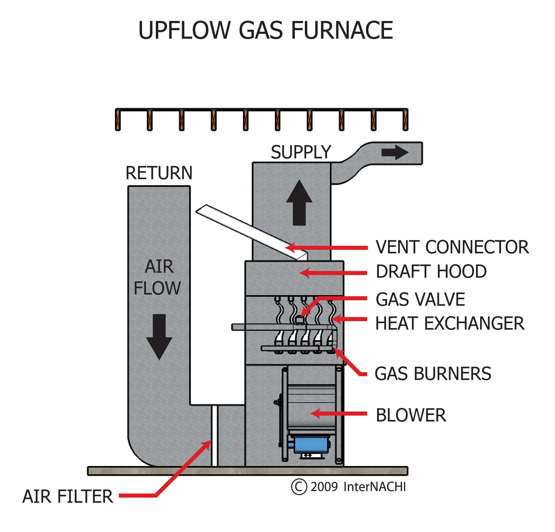
Upflow Gas Furnace - Inspection Gallery - InterNACHI®
PDF Locating and Estimating Air Emissions from sources of dioxins and... Process descriptions and flow diagrams are included in the discussions as appropriate. Minimizing in-furnace generation of CDD/CDF is accomplished by optimizing waste feeding procedures, achieving adequate combustion temperatures, providing the proper amount and distribution of combustion air...

How To Size Heating & Cooling Systems | Hvac furnace, Hvac ...
PDF ENVIRONMENTAL Flow diagram of primary nickel production showinc the number of operations and type of process used flow diagram The furnace consists of a cylindrical brick-lined shell with a grate at the bottom through which air is blown into the furnace at a rate sufficient to hold...
How does a furnace heat exchanger work? - Quora
PDF 523353-UIM-B-0210.fm HORIZONTAL APPLICATION. Gas Furnace. Air flow. Refer to the wiring diagram in this instruction. For additional connection diagrams for all UPG equipment refer to "Low Voltage System Wiring" document available on-line at in the Product Catalog Section.

Furnace Air filter Air conditioning Airflow Rheem, hvac ...
Furnace Air Flow Direction Diagram Search anything about Diagram Ideas in this website. Furnace Air Flow Direction Diagram. Your furnace doesnt create air it simply cycles air from one place to another throughout your home.
Wood Charcoal Making Machine Air Flow Carbonization Furnace ...
How Air Condition Ventilation & Furnace Works - HVAC AC system... Here is my understanding of a HVAC system. I am not a professional, just documenting this and sharing my knowledge. Any comments is appreciated. Thanks for...
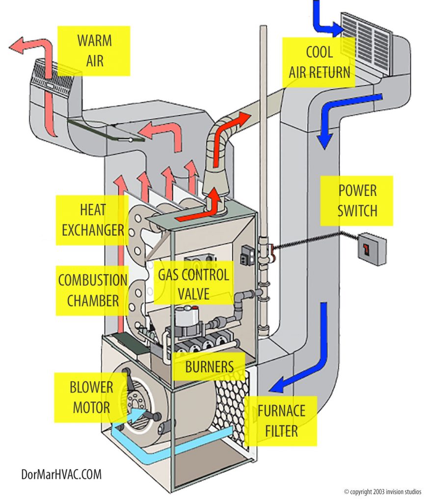
How Does A Furnace Work? - Dor-Mar Heating & Air Conditioning
LIFEBREATH CLEAN AIR FURNACE CAF-02-MB... | ManualsLib Clean air furnace (42 pages). Furnace Lifebreath AH-ELE-15KW-36-E16 Specification Sheet. Page 1 operation, sizing and installation manual clean AIR furnace now manufactured with aircom Page 42: Wiring Diagrams. Wiring Diagram Defrost Freeze...
Gas Furnaces & Heater Troubleshooting Homeowner Checklist ...
Countercurrent exchange - Wikipedia Countercurrent exchange is a mechanism occurring in nature and mimicked in industry and engineering, in which there is a crossover of some property, usually heat or some chemical, between two flowing bodies flowing in opposite directions to each other. The flowing bodies can be liquids, gases, or even solid powders, or any combination of those.

Upflow vs Downflow Furnace - Ultimate Guide
Air flow detector circuit | Circuit diagram with Parts list. This circuit can give a visual indication of the rate of air flow.It can be also used to check whether there is air flow in a given space. variations will be picked up by the opamp (LM339) and the brightness of the LED at its output will be varied proportionally to the airflow.
Application Note Boiler Combustion Air Flow Measurement
en.wikipedia.org › wiki › Fan_(machine)Fan (machine) - Wikipedia The cross-flow or tangential fan, sometimes known as a tubular fan, was patented in 1893 by Paul Mortier, and is used extensively in heating, ventilation, and air conditioning (HVAC), especially in ductless split air conditioners. The fan is usually long concerning the diameter, so the flow remains approximately two-dimensional away from the ends.

Furnace Process flow diagram Spray drying, particle effects ...
My RV Furnace Fan Runs But There's No Heat! Now, What ... 25-10-2021 · Have you ever been in a chilly RV, flipped on your furnace to make the RV nice and toasty, and all you got was a steady flow of cold air? If you’ve experienced what happens when an RV furnace fan runs but there’s no heat, then you understand why we’re sending this post out in advance of the arrival of cold weather.

Four people were taken to hospital with carbon monoxide ...
Required Air Flow from an Electric Furnace - Imperial Units Required air flow rate in an air heating system can be calculated as. The diagrams below are calculated from the equations above and can be used to estimate heat required to rise temperature in air flows.

Changing Furnace Filters? The Homeowner's Guide to the Why ...
181 Process Flow Diagram (PFD) Symbols for... | Vista Projects Our Process Flow Diagram Symbols (PFD) List will help you better understand the PFD symbology on any engineering project. FURNACE 1. HYDROCRACKING. What is a Process Flow Diagram Used for? Process flow diagrams can be used to document a predefined process, improve an...
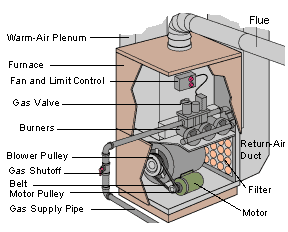
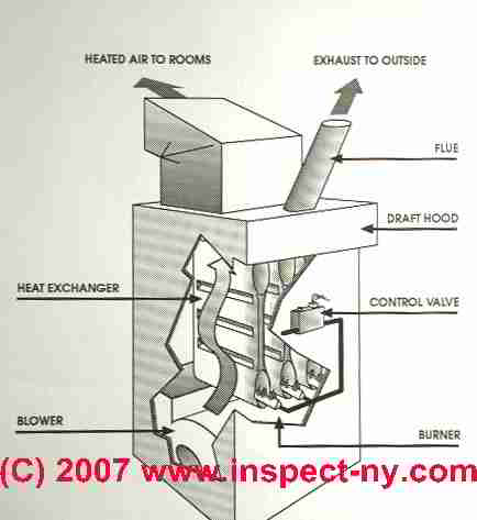
How a Gas Furnace Works
Which Way Does Furnace Air Flow? And Other... - CleanAlert LLC Forced air furnaces recirculate air through a home: pushing air (cool or heated) in, and pulling spent air back in for another cycle. If you are looking at a furnace filter, find the arrow that indicates the proper air flow direction. That arrow must always face toward the furnace and away from the return...

Energies | Free Full-Text | Investigation of Heat Transfer in ...
How To Furnace Air Flow Direction Diagram Details: Air Conditioner Air Flow Direction Diagram / How Do I Know Which Direction To Install My Furnace Filter : Circuit and wiring diagram 20 air Details: Filter Air Conditioner Air Flow Direction Diagram : How To Replace Furnace Ac Filters. This circuit is a visual indication of airflow. (refer to...
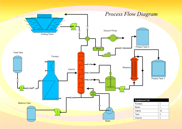
Process Flow Diagram Example - Edraw
Forced Air Outdoor Wood Burning Furnaces and Boilers These air pipes/ducts are only 12″ in diameter so a standard backhoe with a 24″ bucket can easily dig a trench for the pipes to lay side-by-side. A 12″ round duct is equivalent to a duct that is 8″ X 15″ or 10″ X 12″ and you will get the same air flow of 2000 CFM. An 8″ X 12″ or a 10″ X 10″ will give max 1500 CFM.

HVAC Service: Five-Minute Dirty Coil Test | Contracting Business
Humidifier air flow diagram - DoItYourself.com Community Forums I was looking at my current central humidifier, and i was wondering why does the humidifier installed in the cold air intake and taking the warm air from the heater and feed it back to the humidifier then back to the heater again? so here is kinda...
Process Flow Diagram Example - Edraw
THE Corsi/Rosenthal Box FAQ - Clean Air Crew “Generated by body-to-air temperature gradients, human thermal plume creates persistent uprising airflows along the human boundary layer, typically as a laminar-to-turbulent flow with varying thicknesses from 2–4 mm to 200 mm and a maximum velocity of 0.2–0.3 m/s, which is comparable to the designed air velocity in various buildings with mixed ventilation under the …

Furnace Fresh Air Intake 101 - Weather Tech Heating and Cooling
Dometic air conditioner error codes | AC Error Code Air conditioner, furnace, heat strip and fan operation can continue to operate. E5: Open circuit or out of range Freeze Sensor. Air conditioner and dehumidification operation will be locked out. Heat pump, furnace, heat strip and fan operation can continue to operate but displays the last temperature set-point. E6

File:Condensing furnace diagram.png - Wikimedia Commons
Amana Furnace Repair Guide | Troubleshooting, Error Codes ... Make certain that the “air flow” signifiers on the filter are facing the correct direction, towards the blower and away from the cold air. Replace the panel or door to your furnace. Additionally, it’s also important to regularly vacuum vents and check …

Frequent Furnace Problems Could Indicate Your Need for a New ...
PDF E3506E AIR FLOW DIAGRAM. 100 G3506I05. Burner inlet pressure [mbar]. The EMB-SIK burners are supplied with a special furnace wall-fixing flange. The light obtained for the burner hou-sing must 3 - Regulate the air flow using the micrometric pin valve consulting the appropriate setting table.
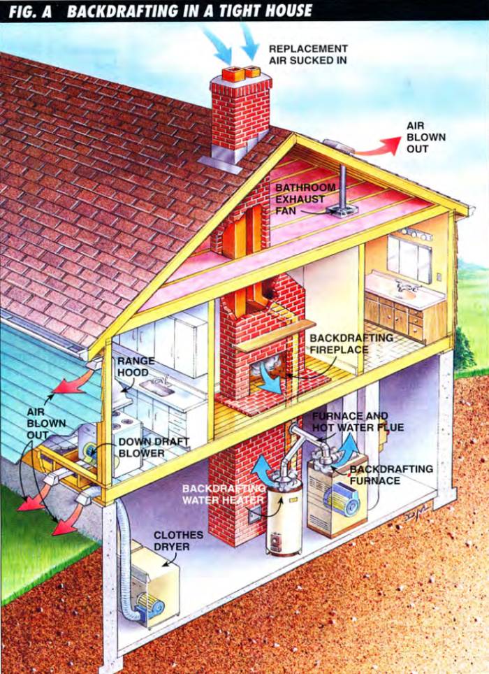
Stop Backdrafting In Your Home Now - BestLife52
(PDF) Industrial and Process Furnaces: Principles... - Academia.edu air ducting 189 Figure 5.37 Example of constant velocity combustion air ducting with weirs 190 Figure 5.38 Effect of single blade damper/air door on of the current 331 Figure 9.1 Schematic diagram of a generic furnace process showing flows through the system 336 Figure 9.2 Plot of typical furnace...

Changing Furnace Filters? The Homeowner's Guide to the Why ...
TEC ALT Process Descriptions and Flow Diagrams | PDF The following are brief descriptions and pictorial Process Flow Diagrams of Selected Ironmaking Processes: 3-2.1 shaft furnace processes The heated air burns the injected fuel and most of the coke charged in from the top to produce the heat required by the process and to provide...

Changing Furnace Filters? The Homeowner's Guide to the Why ...
Trane Replacement Furnace Filters | By Model | FurnaceCompare® 17-04-2020 · If your unit is an upflow model then the air filter is found in the bottom and side of the furnace cabinet. If the unit is a downflow model, then the filter is found somewhere in the duct work. For replacement filters see the chart below, which is based on the air flow configuration and cabinet width. Furnace Filters for the Trane XL90
Biomass Briquette Air Flow Wood Charcoal Carbonization Furnace
PDF Entropy-temperature and transmission diagrams for air V. the AIR flow diagram. VI. Maximum power transmitted through pipes. Entropy-temperature and transmission diagrams for AIR. I. introduction. 1. Preliminary.-In engineering calculations graphical methods not infrequently afford a satisfactory...

Process flow diagram of furnace 200 | Download Scientific Diagram
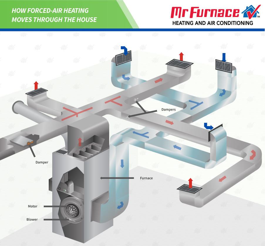
How Does Forced Air Heating Work? - Mr Furnace Right Time
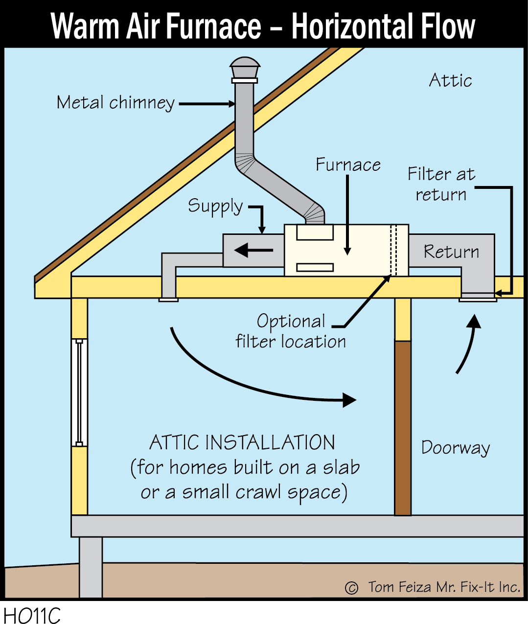
H011C - Warm Air Furnace - Horizontal Flow - Covered Bridge ...
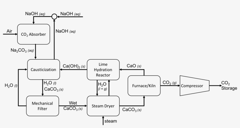
Direct Air Capture Process Flow Diagram Using Caustic ...

7 Steps to Solve Home Airflow Problems - ENGINEERING UPDATES

Furnaces Archives - Page 4 of 4 - Gibbon Heating & Air ...

Install Your Air Filter In the Right Direction To Avoid ...
New and Substantially Improved Buildings CONTENTS Page ...

China Furnace Air Flow Purifier and Duct Cleaning Lab Dust ...

Humidifier air flow diagram - DoItYourself.com Community Forums

How to Figure Out What Is Wrong With Your Furnace - Dengarden

Combustion Air Requirements For Oil Burners | Beckett Corp.

Best Furnace Filters | HVAC DIY Tips

Why is Measuring the Flow of Air and Fuel in a Furnace ...
0 Response to "42 furnace air flow diagram"
Post a Comment