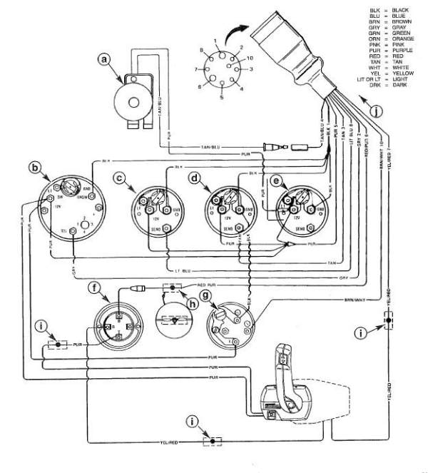
45 mercury control box wiring diagram
Hallo friends I need your help. I have 2007 etec 90HP and I need to conect it with old pre 1996 remote control box with red plug. I will order adapter: ENGINE CABLE ADAPTER KIT# 176349 - 95 BOAT TO 97 but I will have more troubles with system check as this adapter needs extra cable BRP-0176382 to conect to tach with system check. PLEASE IF YOU HAVE WIRING DIAGRAM SHOWING INSTRUMENT AND ...
Mercury Outboard Wiring Harness. Mercury outboard wiring diagrams side mount remote control trim install on fell marine 472 75 and 90 hp models box for 1998 50 elpto single engine controls flush panel vevor boat throttle 881170a15 yamaha rigging 1994 1996 harness mercruiser d4 2l d tronic service manual assembly mercontrol issues any help pls tacklereviewer motor ignition switch f5h268 ...
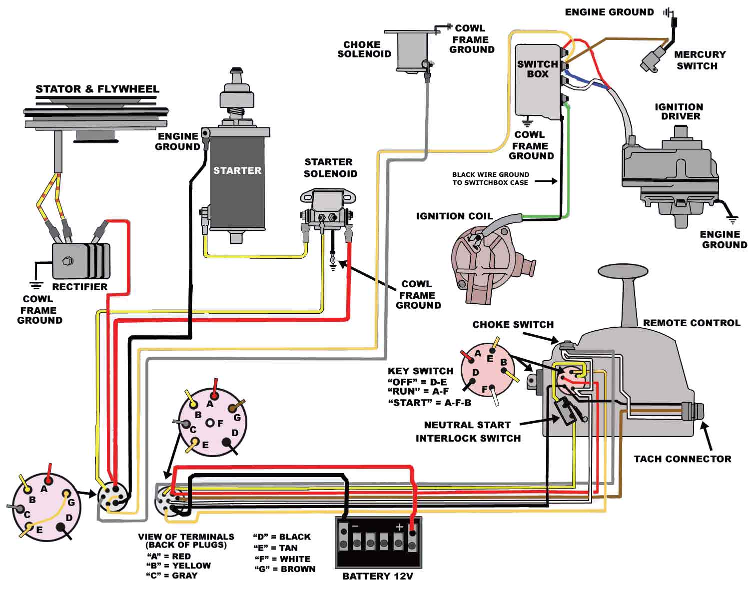
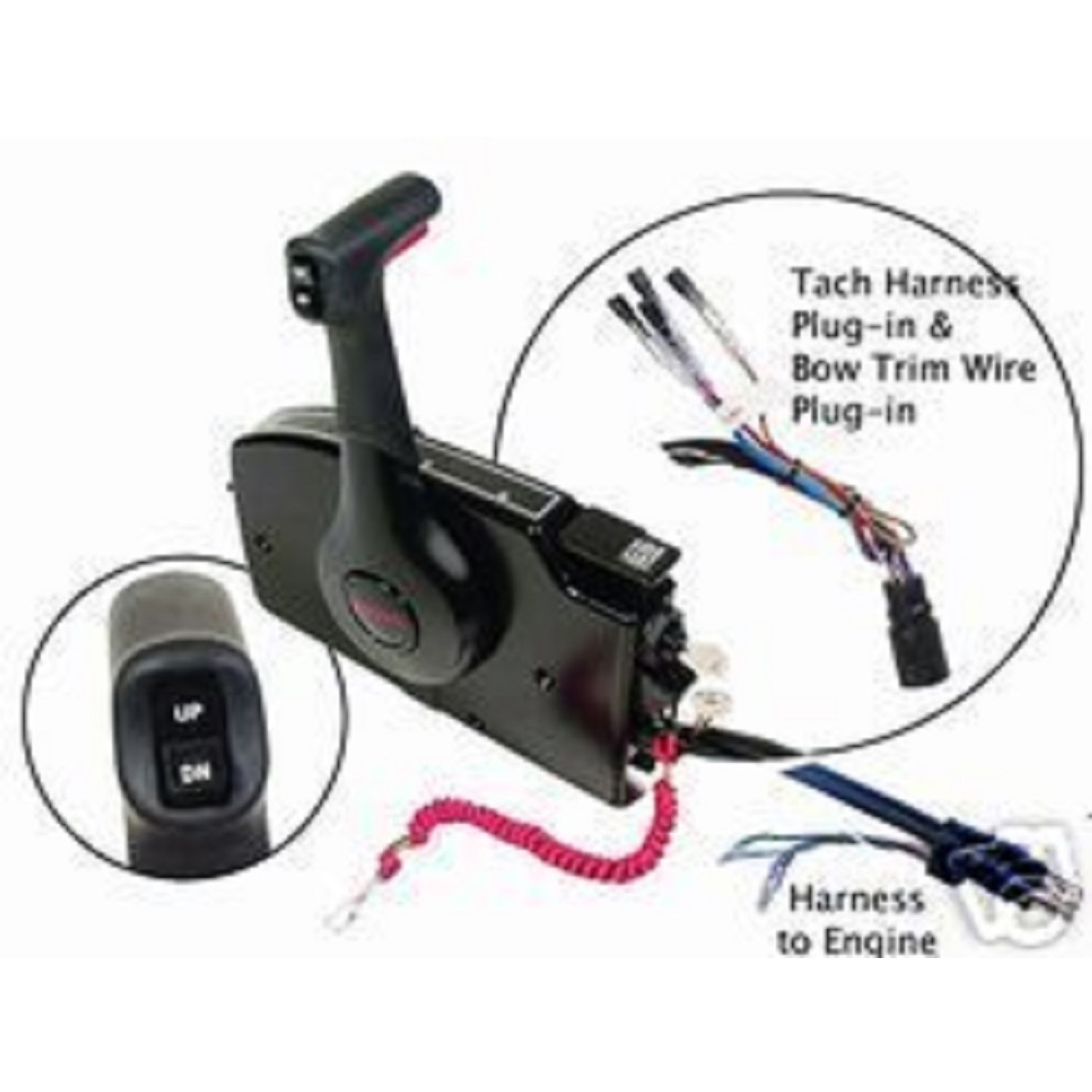
Re: Mercury Control Box With Trim Wiring Question. Yes the 5-pin socket on the front of the controller is for a tach, temp gauge and trim gauge I think. There are often tach harnesses listed for sale on that auction site at reasonable prices. Here are a couple wiring diagrams for your reference. One diagram shows the wiring for a two solenoid ...

Mercury control box wiring diagram
Mercury Marine Technical Library. Our Mercury Marine Parts technical expertise also allows PPT to provide our boating customers with direction regarding Direct Replacement Mercury Outboard Parts options. In certain cases OEM Mercury Marine Parts are the better option but in many cases there are good, economical alternative part options such as with Sierra Marine Parts.
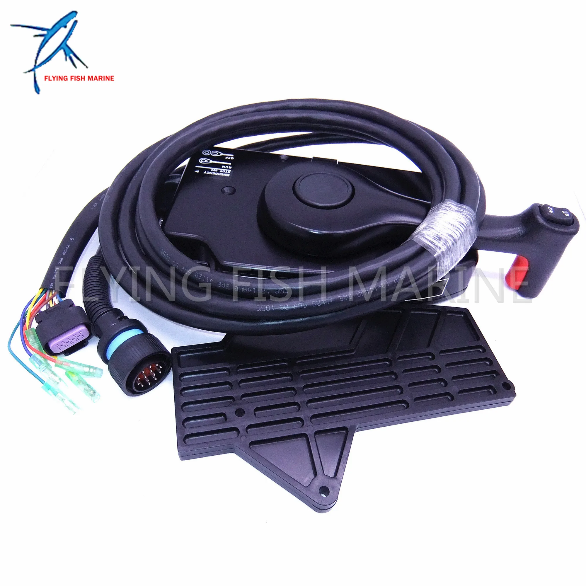
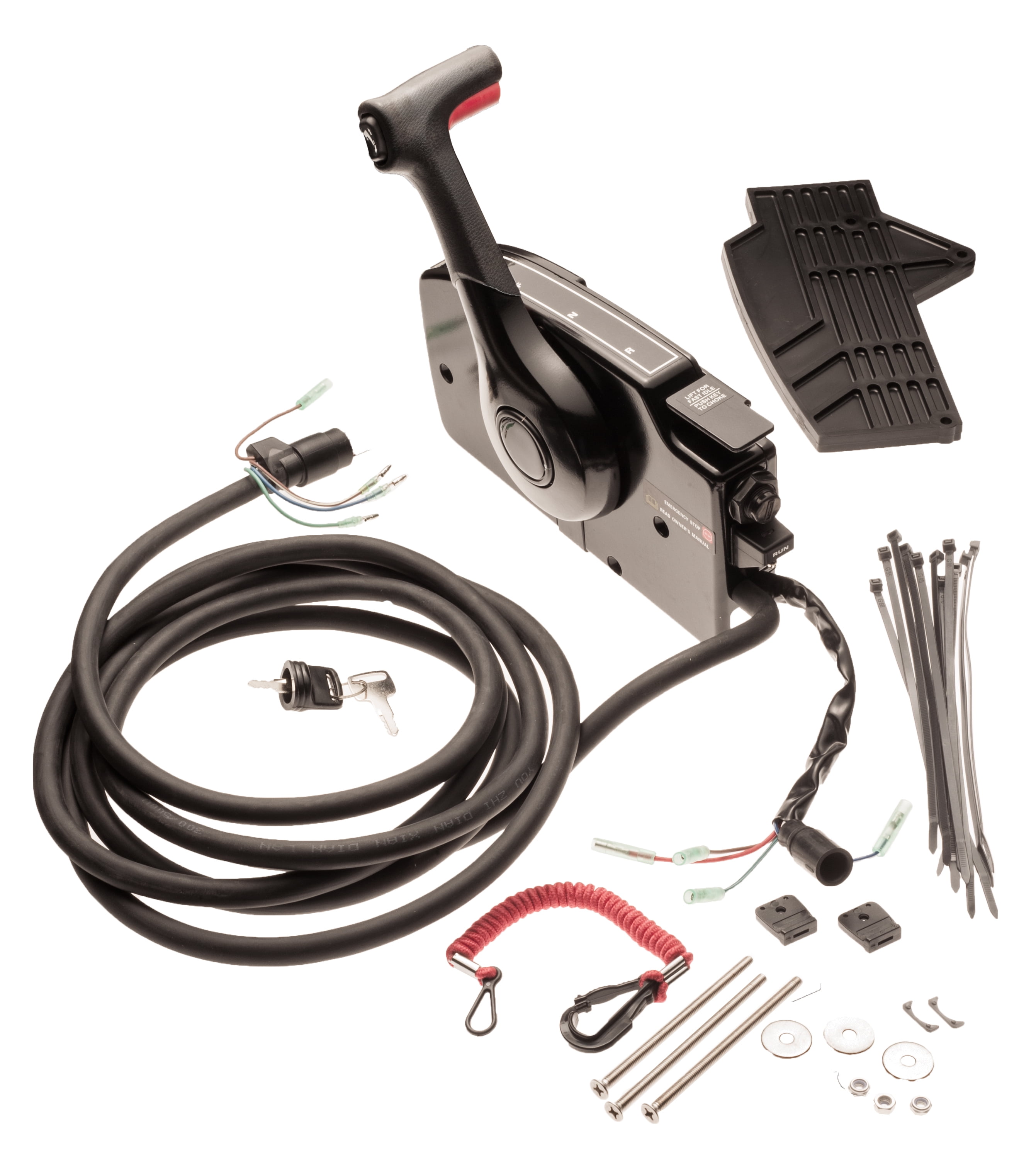
Buy A15 Boat Motor Side Mount Remote Control Box with 8 Pin for Mercury Top Mount Single Engine Outboard Motor Control w/Trim 8M newer 8//15/20 four-stroke outboards an adapter harness A01 is required. Matches OEM wiring and cabling as expected, mounting plate with bolts.Single-Engine Controls.
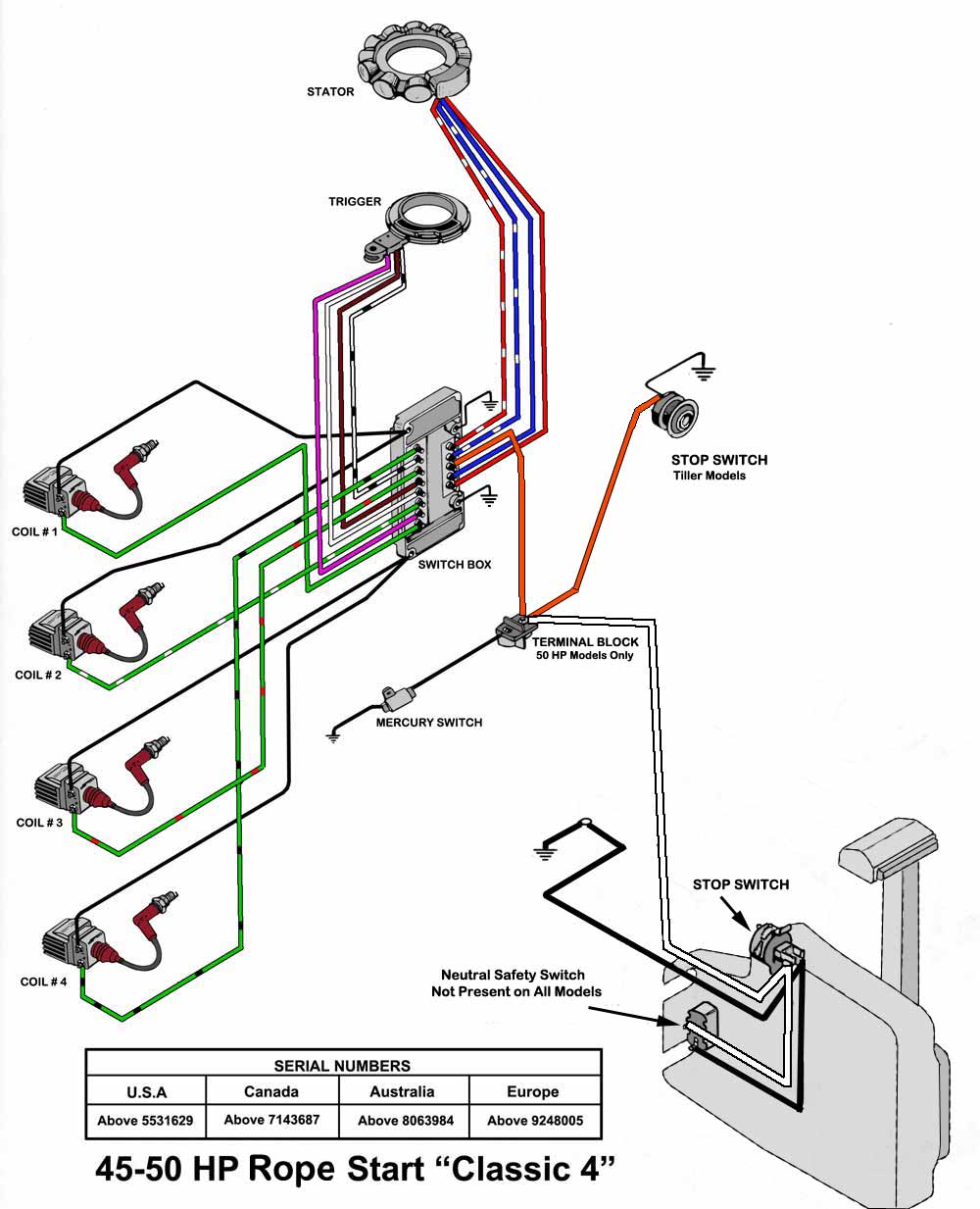
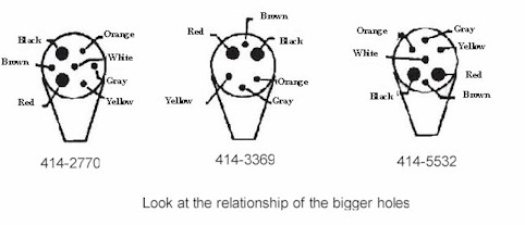
Mercury control box wiring diagram. Instrumentation and controls 90 863758070 april 2008 page 9a 1 9 a. A search with google on the terms 1998 mercury remote control wiring produced this link. What are the color codes for the 14 pin connector.
Mercury control box wiring diagram.
MERCURY ALPHA INSTALLATION MANUAL Pdf Download.. Merc Controls Newest Manual - Free ebook download as PDF File (.pdf), Text File (.txt) or read book online for free., 11/09/2004 · quicksilver throttle/shift control manual September 11th, 2004, 04:43 AM Hi all, I'm looking for the instructions that would have came with the trottle/shift control box common in the late 80's, it's either called ...
Mercury Control Box Wiring Diagram - Agendadepaznarino - Mercury Outboard Wiring Diagram Schematic. Downloads: full (739x1066) | medium (235x150) | large (640x923) Mercury Outboard Wiring Diagram Schematic - mercury outboard wiring diagram schematic, Every electric arrangement is made up of various diverse components. Each component ought ...
June 15, 2018. Mercury Outboard Ignition Switch Wiring Diagram. - Allowed in order to my personal website, in this period I'm going to explain to you in relation to mercury outboard ignition switch wiring diagram. . Now, here is the primary picture:
WMPHE Compatible with Boat Ignition Switch with Key Mercury Outboard Motor Control Box, 3 Position 6 Wire, Sierra MP41070-2, MP41070, MP41070-1, OEM 87-17009A2. $28.99.
The Mercury outboard boat harness (external) is at bottom of this chart. That is the harness that goes from the engine to the control box by the steering wheel. The external harnesses are about 20 feet long.
Mercury Outboard Wiring Diagrams Mastertech Marin. What Instrument Gauges Can Be Hooked Up To 703 Remote Conrol Box. Outboard Engine Wiring Tacklereviewer. Installation Manual D7 3l D Tronic Mercury Marine. Parts Mercury Controls And Rigging Side Mount Remote Control 14 Pin 15ft Wire Harness With Power Trim Black River Boats.
Failure to protect wiring with an appropriate fuse can damage the wiring and start a fire. When installing any accesories, we recommend using a Mercury accessory kit. Always use the appropriate fuse to protect wiring. CAUTION Failure to protect wiring with an appropriate fuse can damage the wiring and start a fire.
Mercury Outboard Kill Switch Wiring Diagram Have Mercury Remote Control Box Dia Full Size single engine controls mercury single engine controls are engineered built and tested for the long run superior quality and workmanship THROTTLE AND SHIFT LINKAGE MERCURY MANUAL FOR MARINER MERCURY 18 20 25 H P XD READ Adipose Tissue Diagram
NEW 14 PIN MERCURY CONTROL BOX WITH 15' CABLE. FITS 8, 9.9 hp, 4-stroke outboards (MY2005 & Newer). 8, 9.9 hp, 4-stroke engines generation change above S/N OR192772 and new 15//20 hp, 4-stroke engines will use Gen I series T/S Cables 25-300 hp, 4-stroke ('06). Fits any engine that has the 14 pin connector from the primary harness.
Re: 2008 Mercury 50ELPTO (2-stroke) w/ 881170A13 Control box - Gauge Options and wiri Thanks carholme! So I've yet to find any wiring schematics or data regarding this engine with a "stock" 14 Pin engine harness and 4000 series commander controller.
Engine Wiring Diagram (3 Cylinder Models with Small COMMANDER Side Mount Remote Control c - Switch Box g - Mercury (Tilt) Stop Switch.A15 - Remote Control, Electric Start, Power Trim Mercury Quicksilver A15 Side Mount Remote Control- 8 pin traditional For power trim models, 15 ft.( m) harness and built-in warning horn.
200 Amp Main Panel Wiring Diagram Electrical Panel Box Diagram Photos Good Pix Gallery Electrical Panel Wiring Home Electrical Wiring Electrical Panel. Mercury Switch Box Wiring Diagram Mercury Outboard Electrical Wiring Diagram Diagram. Junction Box Radial Lighting Wiring Electrical Wiring House Wiring Basic Electrical Wiring.
Mercury's patented Joystick Piloting System delivers 360 degree directional control. The Skyhook Digital Anchoring System holds your boat in a fixed position regardless of wind or current.Active Trim is the only auto-trimming program that uses GPS and speed.SmartCraft DTS (Digital Throttle & Shift) delivers precise and smooth handling with instant response and total control.
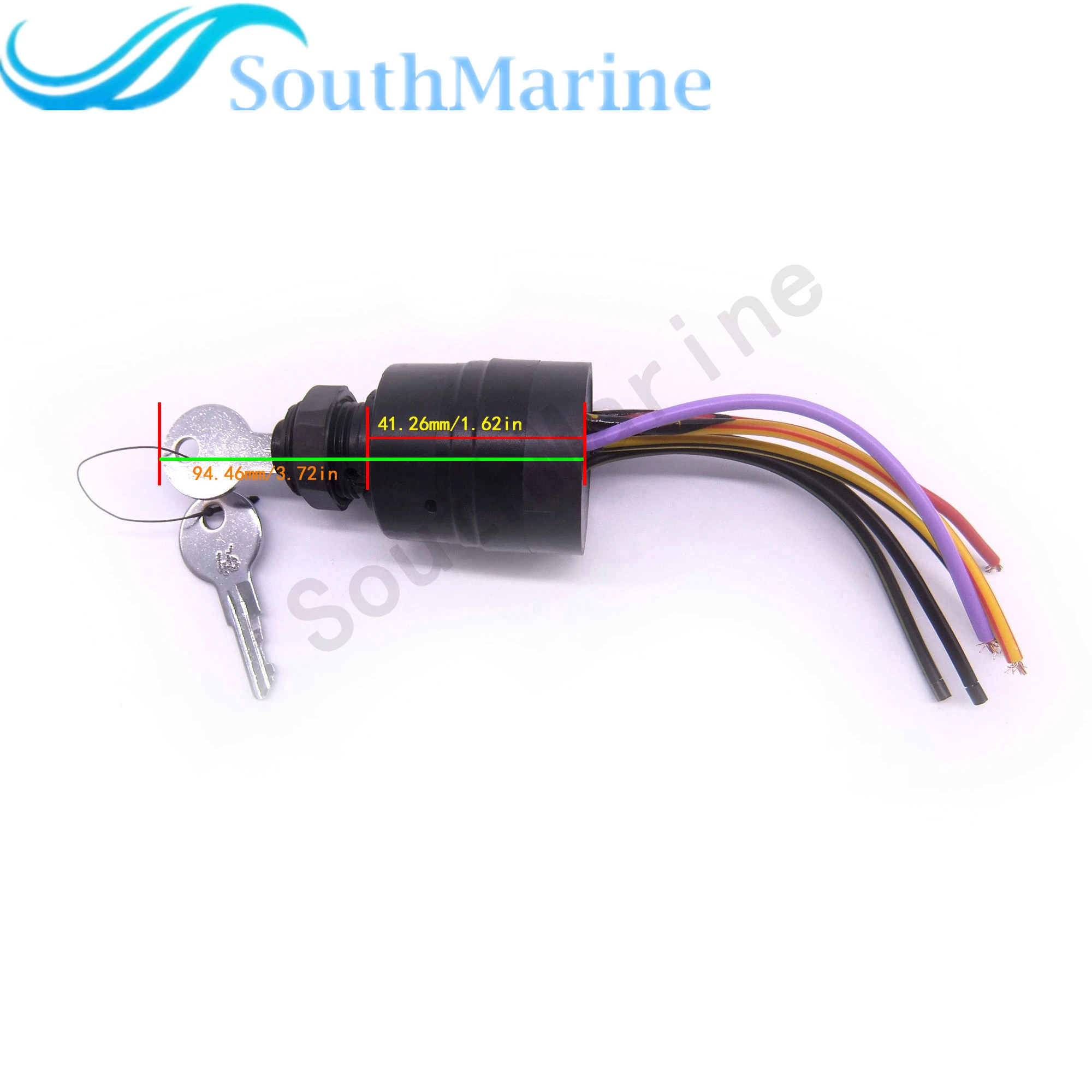
Boat engine 87-17009a2 ignition switch for mercury outboard motor control box , 3 position, 6 wire, sierra mp41070-2
Mercury Outboard Ignition Switch Wiring Diagram. universal ignition switch wiring diagram page 1 iboats re universal ignition switch wiring diagram you are probably looking at ignition switches for an i o outboard switches require more and different ignition coil troubleshooting tips for mercury & mariner mercury mariner ignition coil diagrams coil packs and repair manuals troubleshooting tips ...
• Method 2 - Mercury Marine SmartCraft System View display - If the boat does not have a System View display installed, temporarily connect a System View display to the helm harness as shown in the following wiring diagrams. Follow the DTS calibration setup in-structions. If the DTS system was previously calibrated, perform a DTS system reset

Boat engine 87-17009a2 ignition switch for mercury outboard motor control box, 3 position, 6 wire, fits sierra mp41070-2
Mercury 8 Pin Wiring Diagram - One of the most hard automotive fix tasks that a mechanic or fix shop can take is the wiring, or rewiring of a car's electrical system.The misery in reality is that all car is different. once a pain to remove, replace or repair the wiring in an automobile, having an accurate and detailed mercury 8 pin wiring diagram is indispensable to the expertise of the ...
According to earlier, the traces in a Mercury Outboard Wiring Diagram Schematic signifies wires. At times, the wires will cross. However, it does not mean connection between the wires. Injunction of two wires is usually indicated by black dot to the intersection of two lines.

881170a15 boat motor side mount remote control box with 8 pin for mercury outboard engine pt, left side
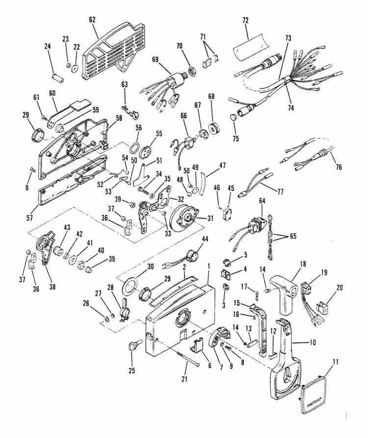
Notes: (Advanced Throttle Only) (A21 And A41). Mercury Marine remote controls and components modular components parts. Buy a genuine Mercury Quicksilver or aftermarket part. Reference numbers in this diagram can be found in a light blue row below — scroll down to order. Each product #9, A 1, THROTTLE LEVER ASSEMBLY (1 required per assembly).
MERCURY WIRING DIAGRAMS. The linked images are printable but may print across more than 1 page (in order to be legible). Most models also have black-&-white-only
Quicksilver 3000 Wiring Diagram. I have a Quicksilver series throttle that has an up and down trim and I'll send you a typical wiring diagram for a Mercruiser trim system. [EBOOK] Quicksilver Series Trim Control Wiring Diagram PDF Books this is the book you are looking for, from the many other titlesof Quicksilver Table of Contents. Page.
Mercury Throttle Control Box Diagram. Mercury Outboard Control Box Wiring Diagram. 50 Hp Mercury Outboard Wiring Diagram. 1979 Mercury 40 Hp Outboard Wiring Diagram. Mercury Outboard 8 Pin Wiring Harness Diagram. Mercury Outboard Gauge Wiring Diagram. Mercury Outboard Key Switch Wiring Diagram.
Mercury Switch Box Wiring Diagram - wiring diagram is a simplified good enough pictorial representation of an electrical circuit. It shows the components of the circuit as simplified shapes, and the facility and signal contacts amid the devices. A wiring diagram usually gives counsel more or less the relative outlook and conformity of devices ...
Mercury Control Box Wiring Diagram. Mercury Stator Wiring Diagram. Ls Wiring Harness Diagram. Yfz 450 Wiring Harness Diagram. Suzuki Outboard Tachometer Wiring Diagram. Yamaha Outboard Key Switch Wiring Diagram. Wiring Harness Pioneer Car Stereo Wiring Diagram. Honeywell Mercury Thermostat Wiring Diagram.

Ignition key switch 87-17009a5 for mercury outboard motors remote control box, 6 wire key starter switch 3-position off-run-start

87-17009a5 boat motor ignition key switch for mercury outboard motors 3 position off-run-start, fit sierra mp51090








0 Response to "45 mercury control box wiring diagram"
Post a Comment