40 ignition coil ballast resistor wiring diagram
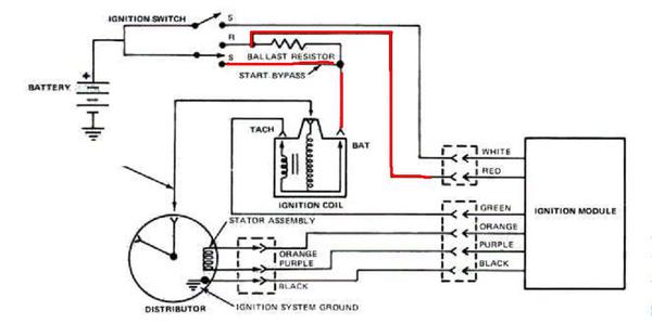
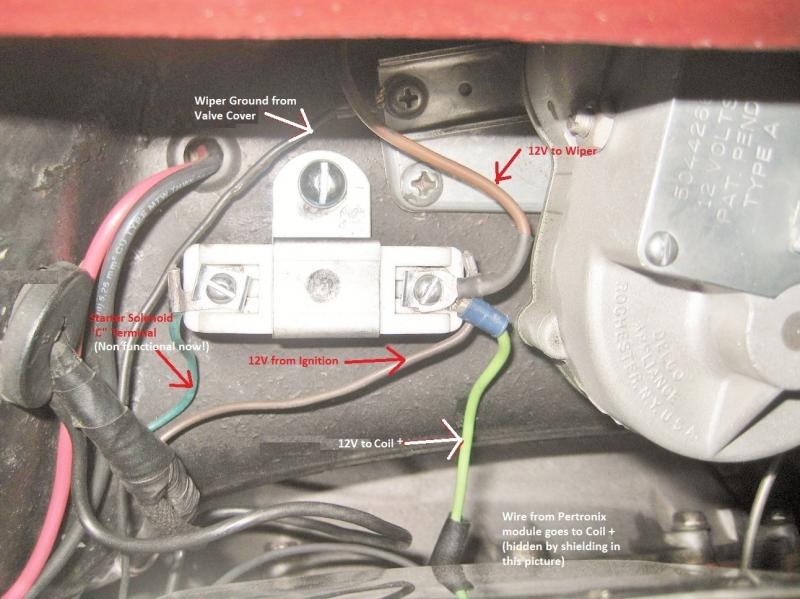
Some customers report that bypassing the ballast resistor by disconnecting the ballast feed wire ( from the starter solenoid or built into the loom) and providing a direct 12 volt feed from the starter solenoid/relay or fuse box to the ignition coil has proved to be a success and has given good results. Jul 07, 2020 · Ignition Coil Ballast Resistor Wiring Diagram Download. A wiring diagram is a schematic type that uses abstract illustrated symbols to show all of the components of a system. Wiring diagrams are made up of two things: symbols that represent the components of a circuit, and lines that represent the connections between them.
Q: Ballast Resistor. ... (coming from the ignition switch) to the ballast resistor but dont connect the wire from the ballast resister to the coil + I have 12.3 volts at BOTH sides of the ballast resistor. Then when I hook the wire from the resistor to the coil my voltage drops back to like 9.6 going in to the resistor and 4.6 coming out and ...
Ignition coil ballast resistor wiring diagram
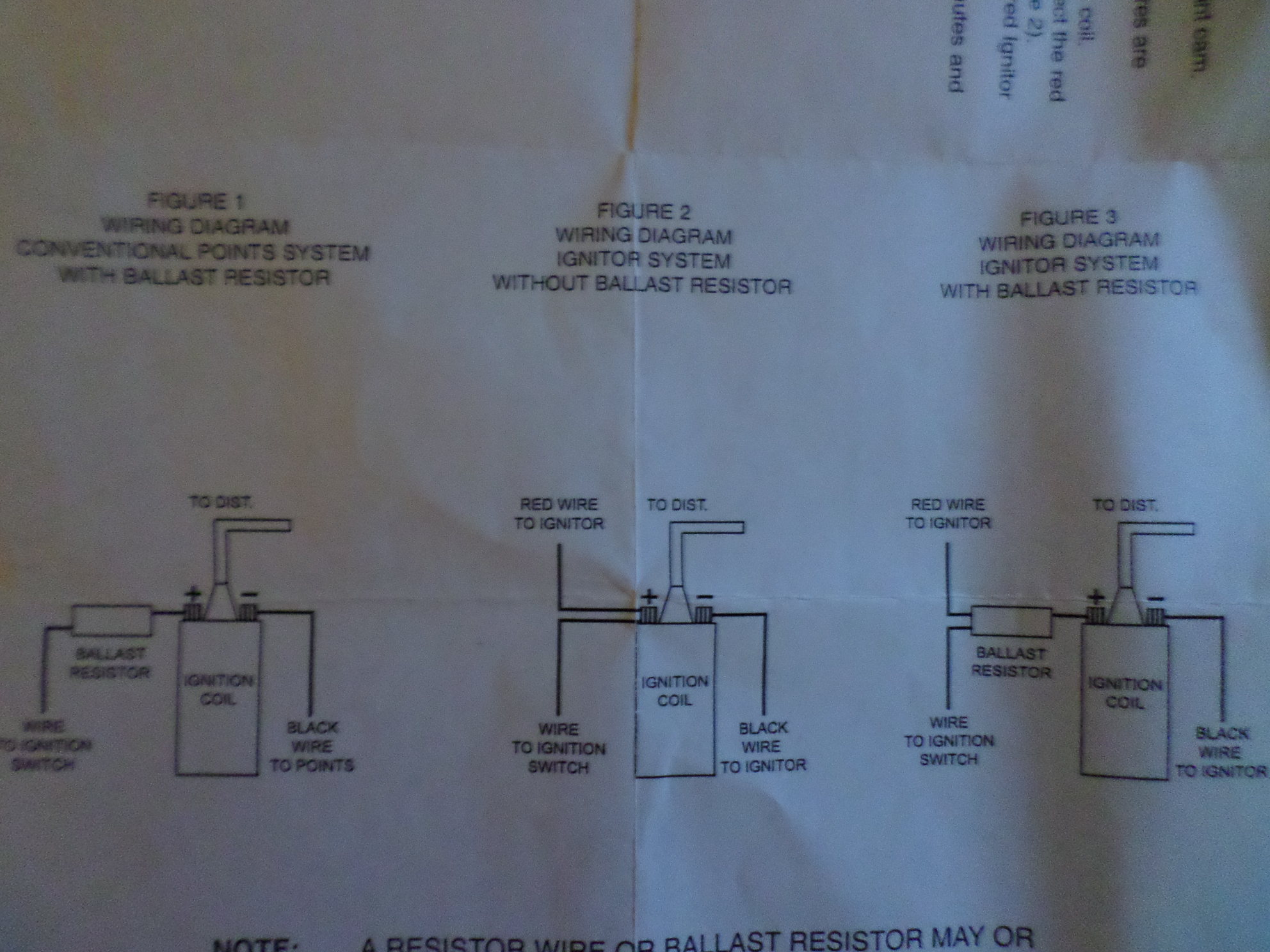
Click to see full answer. Besides, how do you wire a resistor to a coil? Connect a wire from the coil positive terminal to one side of the ballast resistor.Connect 12 volts to the other terminal of the resistor.3. Install the high voltage coil wire.. Also, does an ignition coil need a resistor? Pete, most coils need the resistor Although that's not the case with EVERY coil, most do require it. Dec 15, 2020 · Ignition Coil Ballast Resistor Wiring Diagram from i.pinimg.com. Print the cabling diagram off plus use highlighters to be able to trace the circuit. When you use your finger or even follow the circuit together with your eyes, it is easy to mistrace the circuit. 1 trick that We use is to print the same wiring picture off twice. Jun 8, 2019 - Looking for information about Ignition Coil Distributor Wiring Diagram? you are right here. You may be a professional who wishes to search for referrals or fix existing problems. Or you are a trainee, or maybe even you who just wish to know about Ignition Coil Distributor Wiring Diagram. Coil To Distributor Wiring Diagram – Wiring
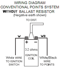
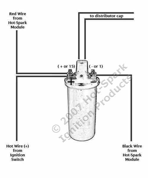
Ignition coil ballast resistor wiring diagram. The typical automotive ignition system prior to 1974 consisted of a coil and ballast resistor, with breaker points to interrupt the current flow when a spark was needed. The job of the ballast resistor was to inhibit current to a level that would not overheat the coil. This simple system is easy for even the novice mechanic to wire. A ballast resistor is a resistor inserted into a circuit to compensate for different changes. The coil does not go direct to earth. Mopar Ballast Resistor Wiring Diagram Basic Electronics Wiring Diagram I am planning to replace the distributor with a mallory unilite pointless distributor the instructions emphasize the necessity of either a ballast resistor […] Jan 04, 2016 · Description: Ignition Coil Ballast Resistor Wiring Diagram regarding Ignition Coil Ballast Resistor Wiring Diagram, image size 1043 X 697 px, and to view image details please click the image. Description : Ignition Coil Ballast Resistor Wiring Diagram – Facbooik pertaining to Ignition Coil Ballast Resistor Wiring Diagram, image size 768 X 576 px, and to view image details please click the image. Mar 21, 2021 · Hot spark electronic ignition accuspark wiring diagrams ballast resistor bmw 2002 igniter and with resistors for c bos only help ford how to replace a troubleshooting 1956 f100 coil low voltage Compatible Ignition Coils Ballast Resistors Hot Spark Electronic Accuspark Wiring Diagrams No Brainer Wiring Question Ballast Resistor Bmw 2002 And Other 02 Faq Igniter… Read More »
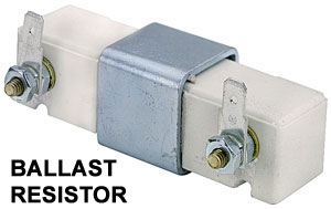
Step 4: Install Ballast Resistor. Set the ballast resistor up to the firewall and screw the clamps in place. Step 5: Connect Wires to Positive. Strip the end of the positive wire from the ignition, and connect it to the positive end of the resistor. From the other terminal on the resistor a wire goes to the positive on the coil. May 23, 2021 · Diagram Wiring Diagram Ballast Resistor Ignition Coil Full Version Hd Quality Ignition Coil Wiringout Aube Siae Fr . In a points type ignition the ballast resistor would help to keep the spark down and the coil from being burned up too quickly. Ballast resistor wiring diagram points. Accel points eliminator wiring diagram using oem primary resistance wire figure 4 distributor distributor wire harness red brown ground to engine block green must use supressor coil wire accel ballast ignition ... Jun 8, 2019 - Looking for information about Ignition Coil Distributor Wiring Diagram? you are right here. You may be a professional who wishes to search for referrals or fix existing problems. Or you are a trainee, or maybe even you who just wish to know about Ignition Coil Distributor Wiring Diagram. Coil To Distributor Wiring Diagram – Wiring Dec 15, 2020 · Ignition Coil Ballast Resistor Wiring Diagram from i.pinimg.com. Print the cabling diagram off plus use highlighters to be able to trace the circuit. When you use your finger or even follow the circuit together with your eyes, it is easy to mistrace the circuit. 1 trick that We use is to print the same wiring picture off twice.
Click to see full answer. Besides, how do you wire a resistor to a coil? Connect a wire from the coil positive terminal to one side of the ballast resistor.Connect 12 volts to the other terminal of the resistor.3. Install the high voltage coil wire.. Also, does an ignition coil need a resistor? Pete, most coils need the resistor Although that's not the case with EVERY coil, most do require it.








0 Response to "40 ignition coil ballast resistor wiring diagram"
Post a Comment