44 emergency lighting wiring diagram
Emergency Light Wiring Diagram from lightwiring.co.uk. Print the cabling diagram off and use highlighters in order to trace the routine. When you make use of your finger or even stick to the circuit with your eyes, it's easy to mistrace the circuit. 1 trick that I 2 to print out the same wiring diagram off twice. ELCU's Normal wiring leads to the normal lighting circuit as shown in the wiring diagram. Note that the Normal Power Sense connection should be made to the line side of the control device that serves the same area as the emergency lighting. This ensures that the emergency lighting in the controlled
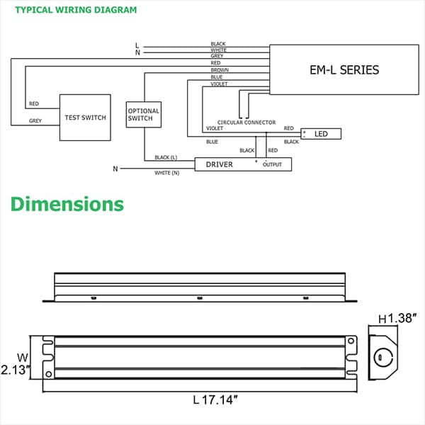
WIRING DIAGRAM REMOTE CAPABLE REGULAR 1. During an electrical power failure, the LED lamps will automatically come on for a minimum of 90 minutes. 2. To test, depress the "TEST" switch. The emergency LED lamps will illuminate. When the switch is released, the lamps will go off. BLUE(-) YELLOW(+) BLUE(-) BLUE(-) YELLOW(+) LAMP YELLOW(+) LAMP ...

Emergency lighting wiring diagram
THE EMERGENCY BALLAST WIRING GUIDE This Document has been customized to contain a wide library of individual dia-grams for various installation applications. If a diagram cannot be found within this selection, consult Customer Service. The diagrams are categorized primarily according to the number of lamps in the Fluorescent Emergency Ballast Wiring Diagram Sample. fluorescent emergency ballast wiring diagram - A Novice s Overview to Circuit Diagrams A very first consider a circuit diagram could be confusing, yet if you could review a train map, you could read schematics. The function coincides: obtaining from point A to aim B. Literally, a circuit is the… orange wire must be capped with wire nut or other approved » » insulator. Failure to do so may cause an unsafe condition. .«» 9. Secure the Canopy to the Mounting Bracket with supplied screws. 10. Turn on AC power. To Remove Directional Indicators: Use your fingers or a soft tool to tap out the WIRING DIAGRAMS desired chevron from its position.
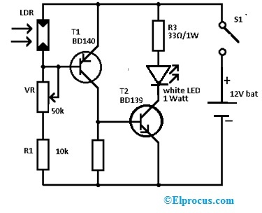
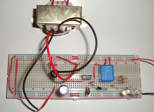
Emergency lighting wiring diagram. The DIY emergency light can be designed in a step by step process like the following. The required components of the 12v emergency light circuit diagram mainly include LDR, 50K VR, 10K Resistor, BD139 & BD140 transistor, 33ohm resistor, and white LED and 12V battery. Connect the circuit on the breadboard as per the diagram shown below using the ... wiring diagrams for 2-lamp emergency operation (2´- 4´, 17- 40 w lamps only) wiring diagram for 1-lamp emergency operation emergency ballast and ac ballast must be fed from the same branch circuit typical schematics only. may be used with other ballasts. consult the factory for other wiring diagrams. e m e r g e n c y b a l l a s t wall ... Emergency Lighting Mini Central Inverter System (Black) (Blue) (White) (Violet) Switched Command Signal (Not Suitable Dimming Circuits. Use Diagrams 3-6) (White) Earth Ground (Green) Input Wiring Neutral Line Line Output Wiring Switch Device (No Dimmers) Light Fixtures (LED, HID, Incandescent or Fluorescent) *Cap off unused wires Diagram #2 Non Maintained Emergency Lighting Wiring Diagram- wiring diagram is a simplified good enough pictorial representation of an electrical circuit.It shows the components of the circuit as simplified shapes, and the capacity and signal connections in the company of the devices.
Variety of emergency exit light wiring diagram. A wiring diagram is a streamlined traditional pictorial representation of an electric circuit. Maintained Emergency Lighting Wiring Diagram. Fixed and wire suspended led exit sign r uk emergency test switch installation lighting circuits connections for solar light circuit diagram wiring ld ldpro guidelines testing user s guide lights battery guard maintained. Mexlite Fixed And Wire Suspended Led Exit Sign Emergency Lighting Products Ltd. THE EMERGENCY BALLAST WIRING GUIDE This Document has been customized to contain a wide library of individual dia-grams for various installation applications. If a diagram cannot be found within this selection, consult Customer Service. The diagrams are categorized primarily according to the number of lamps in the see wiring diagram - note 2 white common ballast hsg see note 3 under wiring diagram make connection for charge indicat or ballast cover emergency ballast lighting fixture models: wgc42fe c942fe nrg304be black, hot 1 120 or 277vac unswitched test switch/charge indicat or 4) see wiring diagram for required connections. swit ched unswit ched 120 ...
Emergency Light Testing made easy What is Emergency Lighting Test Switch The NHP Concept Emergency Lighting Test switch kit allows quick and easy method to semi automate discharge testing of single point emergency lighting fittings in accordance with AS/ NZS2293.1 and AS/NZS 2293.2 "Emergency evacuation lighting for buildings". • UL listed Emergency Lighting and Power Equipment; five year warranty ELCU Wiring Diagrams Jumper Wire or Normally Closed Input from • Test Switch • Fire Alarm Input • Security Input • Other Remote In Switch In Line Neut. In Normal Power Emergency Power Line Out In Neut Emergency Lighting Emergency Line Emergency Neutral "Sensing" Line wiring diagrams: dual head emergency lighting fixture battery 6v 4.5ah 6v 5.4w lamps p.c.b. standard wiring diagram: 277v red or orange black white red (+) blue (-) 120v com battery 6v 4.5ah 6v 5.4w lamps p.c.b. wiring diagram (with heater): 277v red or orange black white red (+) blue (-) black 120v com white 120v com heater. title: r1_1.eps ... 2) if the emergency lights need to be tested, only the supply to the emergency lights needs to be interrupted. In practice you will have fish tail key switches in the power supply leading to suitable groups of emergency lights so that you don't have to switch off the power at fuse level when you want to check your emergency lighting as this ...
An Emergency Lighting Circuit Diagram Printed Circuit Board Manufacturing Pcb Assembly Rayming
Diagram in pictures database 4 lamp t8 emergency ballast wiring just or read 168 forum onyxum com cooper lighting full version hd quality easyplugwiring aube siae fr xy 9317 led driver instructions 1 60w 220 310vdc for sanforce shenzhen sunwind co ltd al 7490 power supply circuit on light diagrams cosine developments universal everline ...

Emergency Exit Sign Wiring Diagram Gallery Laptrinhx News
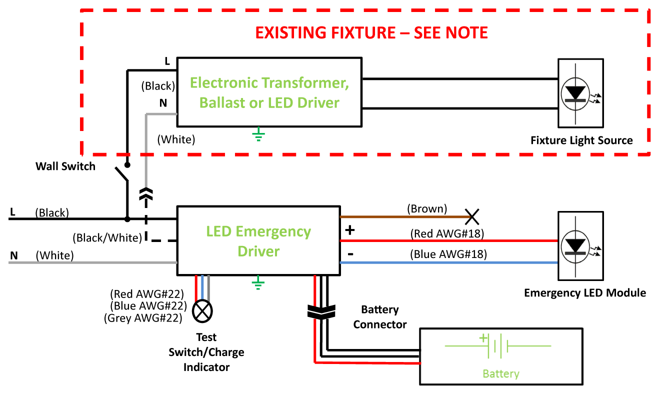
First, identify the electrical voltage of the connection that is being made to the emergency light fixture, either 120 or 277 volt. Next, examine the connections on the unit, there will be 3 or 4 wires which will be colored and labeled: 120v wire (black) 277v wire (red) Common wire (white)
2
Elp Alternate Wiring Diagrams Hatch Lighting. Fat led f1a emergency pack lighting inverter wiring diagram 10 light circuit an r uk test switch installation home lights upshine testing automatic 3 simple many elp alternate diagrams hatch circuits electronic with dimming control mini sigmatone the advantage design in guide user manual manualzz ld ldpro guidelines cat no 682083 connections for ...

Relay Connection And Wiring Diagram For Emergency Light Etechnog
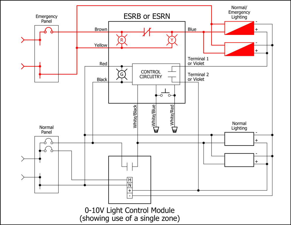
emergency lighting control has been an ongoing debate, coupled with changes to codes and standards, as well as an increased market awareness of the issues. As such, we thought it was time to update the original 2004 material. For some time, the proper control of emergency lighting circuits has been a topic of hot debate for manufacturers, systems
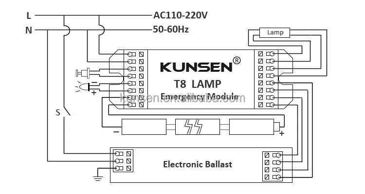
Led Emergency Light Module For Tube T8 Tube 90 Minutes On Emergency Mode Weyes
https://ryb.com.bd/ visit my website http://rybonline.com/ emergency light switch wiring diagram! Switches and Emergency Lighting RYB ELECTRICALবিদেশে ...

Emergency Lighting Wiring Set Up Question Answer Board Talk Electrician Forum
Wiring Diagrams — Common Lightcloud Wiring Applications 8 Any wires not in use must be capped o or otherwise insulated. This product should only be installed by a qualified electrician and in compliance ! with local and national electrical codes. Emergency Lighting Lightcloud Controllers can be used to control Emergency Lighting fed with
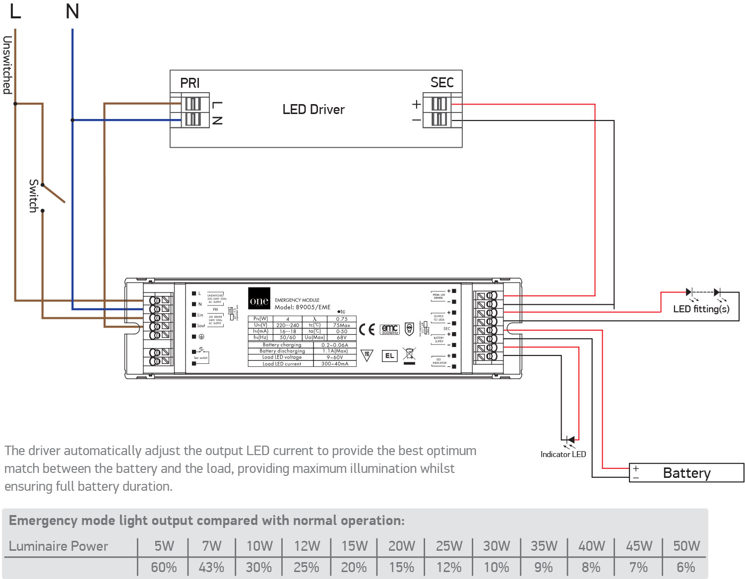
89005a Eme One Light
Jitender Screwfix Select. I have upload a circuit diagram below, I have purchased a Fern Howard emergency light maintained. This is the datasheet for the luminarire. It would still require a 3 core cable as it needs a permanent live and switched live. Jitender, Aug 18, 2015.
Emergency Light Circuit Diagram Working And Its Applications
Wiring diagrams 6 Reference and specifications table 7 Order forms 8 Accessories 9 Monitoring unit 10 DaisaTest System 22 Luminaires for centralised units 24 Pages ... units for emergency lighting . in switched mode or without breaker are designed and built in accordance with EN 50171. It is a centralised unit with 230

Emergency Lighting Wiring Diagram Electrical Wires Cable Residual Current Device Electrical Network Emergency Light Electrical Wires Cable Schematic Electrical Switches Png Pngwing
Emergency light is an integral part of household electronics nowadays. We all know Emergency light is used during the power failure to light up the home. As it is used during the power failure, it should last long, hence generally bright white LEDs are used in emergency light, because they produce more light and consume less power.

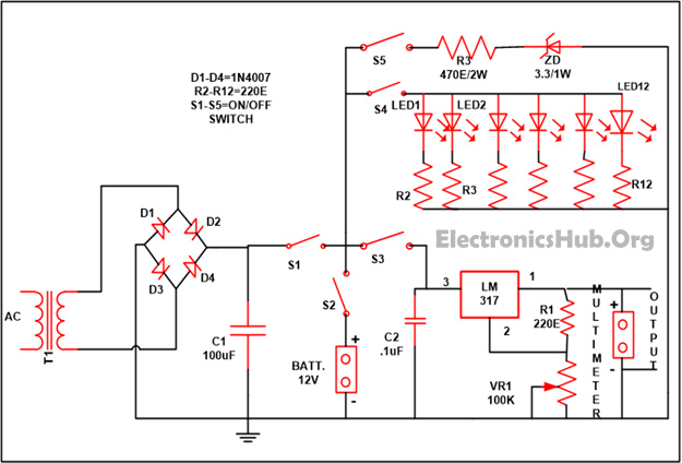
Circuit Book Free Ac 220v Mains Powered Emergency Light And Alarm
function that simulates utility power failure and holds emergency lighting on for 2.5 seconds each time the switched input is turned OFF. SPECIFICATIONS Refer to LVS Controls, Inc, Installation Instructions and product labels for specifications and load ratings. WIRING DIAGRAMS - LX and CX Panels, Power Packs and wiHUBB Smart Packs
2
IIRC the last time different methods of wiring emergency lighting were discussed it got pretty heated. I agree the 'cut live method' isn't the best in all situations, ie turning nearly all the lights off in an officefull of women can cause them to panic and moan, but if you can get into a room to do the test when it's unoccupied it's easier to ...
1
orange wire must be capped with wire nut or other approved » » insulator. Failure to do so may cause an unsafe condition. .«» 9. Secure the Canopy to the Mounting Bracket with supplied screws. 10. Turn on AC power. To Remove Directional Indicators: Use your fingers or a soft tool to tap out the WIRING DIAGRAMS desired chevron from its position.
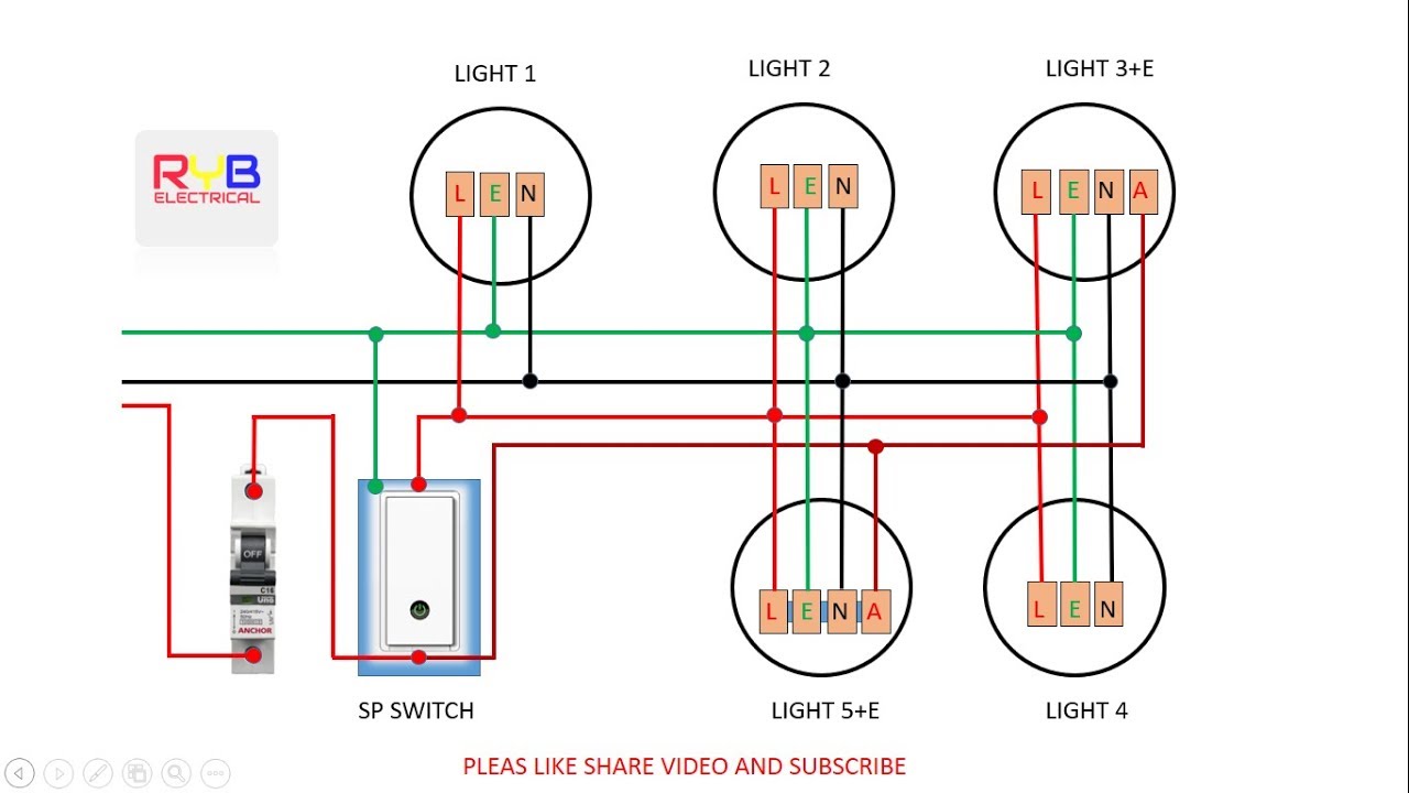
Emergency Light Switch Wiring Diagram Youtube
Fluorescent Emergency Ballast Wiring Diagram Sample. fluorescent emergency ballast wiring diagram - A Novice s Overview to Circuit Diagrams A very first consider a circuit diagram could be confusing, yet if you could review a train map, you could read schematics. The function coincides: obtaining from point A to aim B. Literally, a circuit is the…

Emergency Lighting Products Dali And Self Test Functionality
THE EMERGENCY BALLAST WIRING GUIDE This Document has been customized to contain a wide library of individual dia-grams for various installation applications. If a diagram cannot be found within this selection, consult Customer Service. The diagrams are categorized primarily according to the number of lamps in the
Led Emergency Battery Backup For Led Flat Panel Troffer T8 Chiuer

Fat Led F1a Led Emergency Pack Connection Wiring Diagram Easy To Install This Model Suitable For Led Lights With External Led Driver Contact Led Emergency Light Emergency Power Supply Source Manufacturer Facebook

Automatic Emergency Light Circuit
Battery Emergency Pack Inverter Emergency Kits 18 70w With High Frequency Ballast Buy Battery Emergency Pack Inverte Lamp Emergency Inverter Kit Emergency Kit For Fluorescent Light Product On Alibaba Com
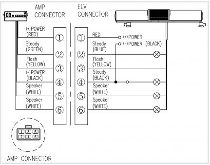
Light Bar For Emergency Car Qlight
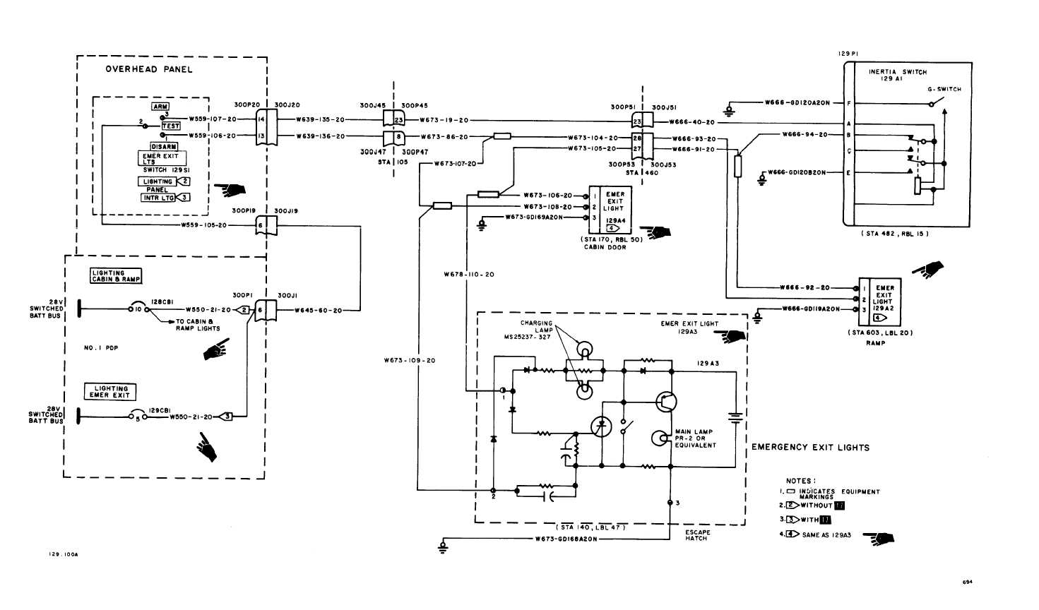
Emergency Exit Lights Wiring Diagram
Emergency Light Circuit Diagram

Battery Guard For Emergency Lights
Emergency Lighting Wiring Diagram Png 2048x1471px Light Circuit Diagram Diagram Electrical Ballast Electrical Network Download Free

Nhp Cpelk1w Emergency Light Test Kit Rotary Switch Wired Open Type For Sale Online Ebay
2
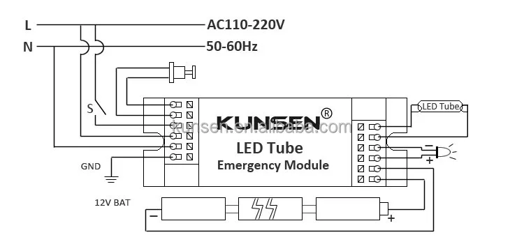
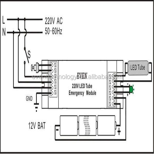
230 Volt Ac Output Rechargeable Led Emergency Light For Led Tube With Battery Backup Buy Rechargeable Led Emergency Light Automatic Led Emergency Light Led Emergency Lighting Product On Alibaba Com
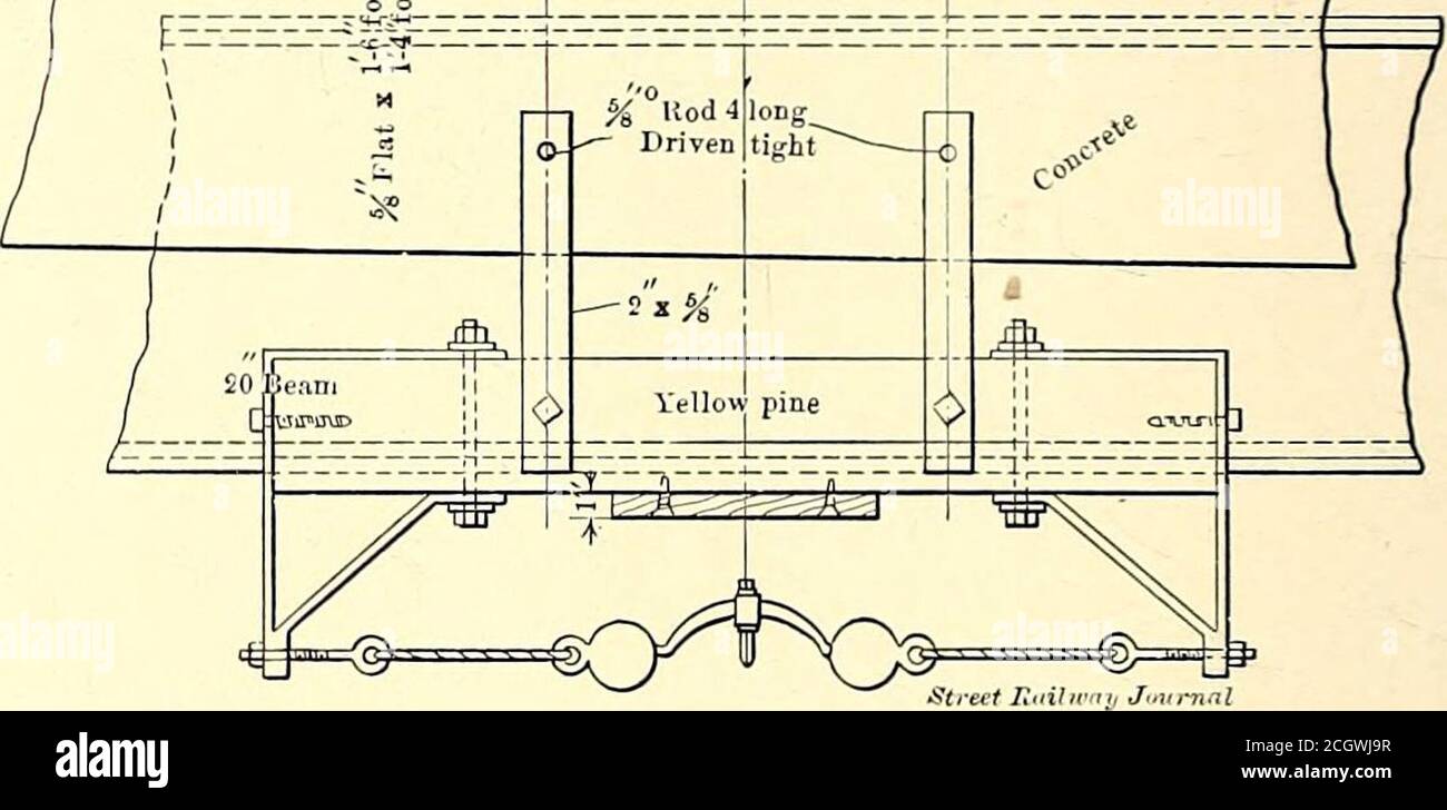
The Street Railway Journal Me Ofthe Nineteenth Streetstation The Principal Lights Are Arranged To Be Supplied From The Lighting Transformer But On Each Plat Form And On Every Stairway There Is
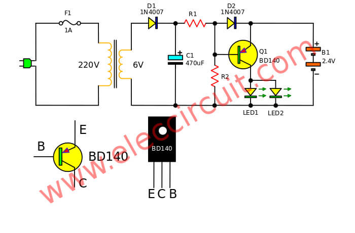
3 Simple Emergency Light Circuit Many Ideas Mini And 12v Eleccircuit

Non Maintained Emergency Lighting Wiring Diagram Emergency Lighting Led Tubes Lighting

50 Luxury Emergency Light Wiring Diagram Emergency Lighting Diagram Emergency

Ceiling Rose Wiring Older Cable Colours Ceiling Rose Wiring Diagrams

Emergency Lighting Test Switch Legrand Emergency Lighting Test Switch Cat No 682083 And 682084

Emergency Lighting Wiring Diagram Electrical Ballast Power Inverters Png 1666x450px Light Area Brand Circuit Diagram Diagram
Emergency Lighting With Dimming Control Functional Devices Inc
2

Mexlite Fixed And Wire Suspended Led Exit Sign Emergency Lighting Products Ltd
Elp Alternate Wiring Diagrams Hatch Lighting

Wiring Diagram For Emergency Light Fitting Budaktakmatangpunyecerite

Filling Diagram Simple Emergency Light

Wiring Diagram
Highlight Packet Hired Auto Cut Off Emergency Light Circuit Paper4pens Co Uk
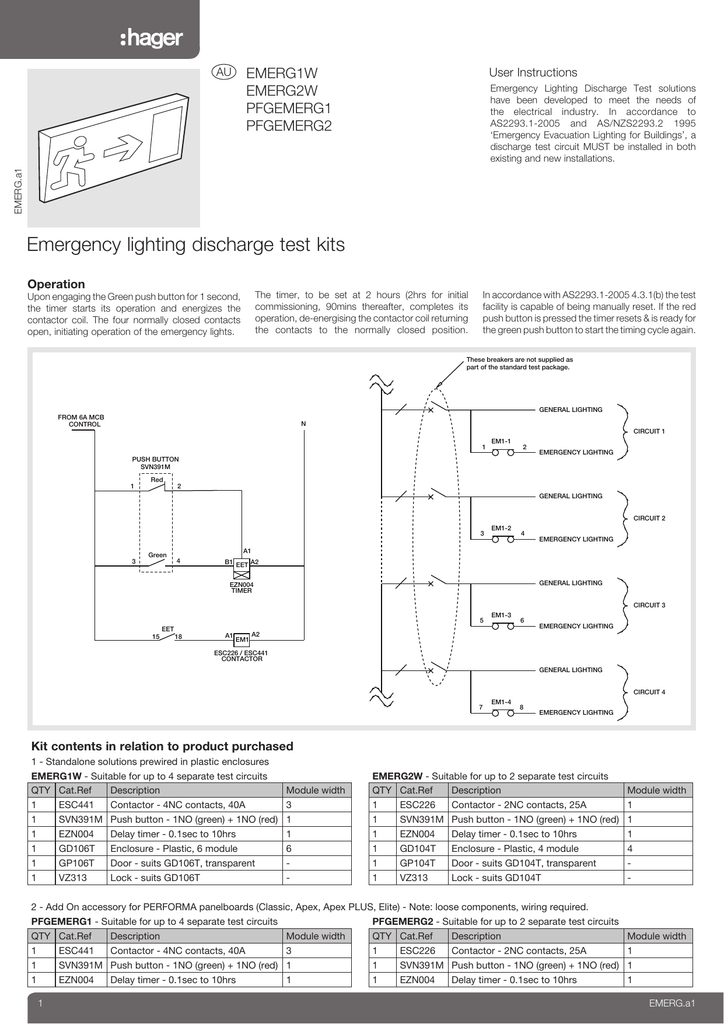
Emergency Lighting Discharge Test Kits
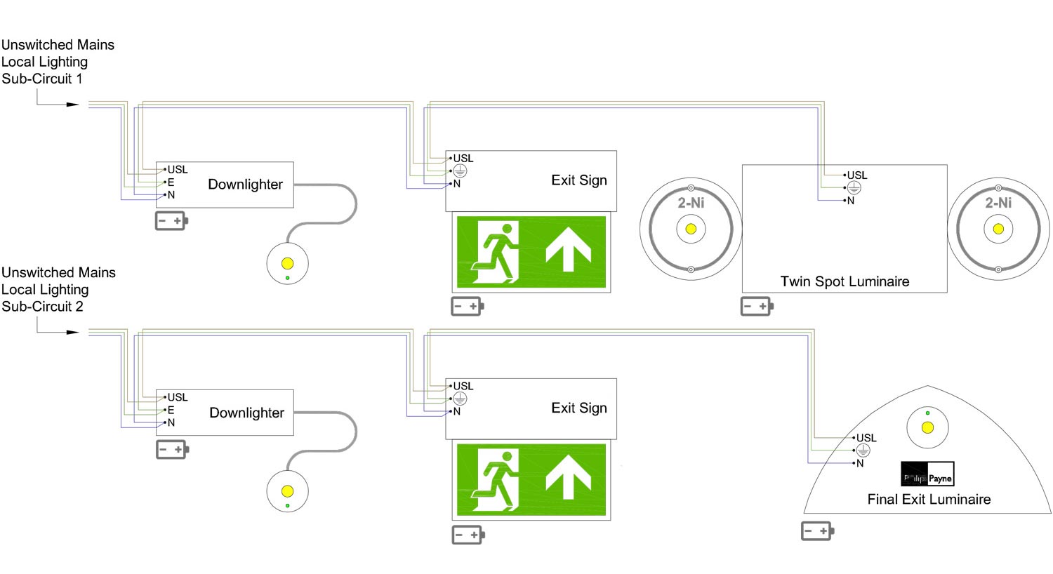
Self Contained Or Central Battery Back Up Emergency Lighting How To Choose Philip Payne

Jual Emergency Samcom Emk 140 L5c Fluorescent Lamp Cahayaglodok Com
0 Response to "44 emergency lighting wiring diagram"
Post a Comment