40 water pump pressure switch diagram
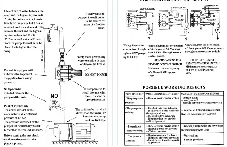
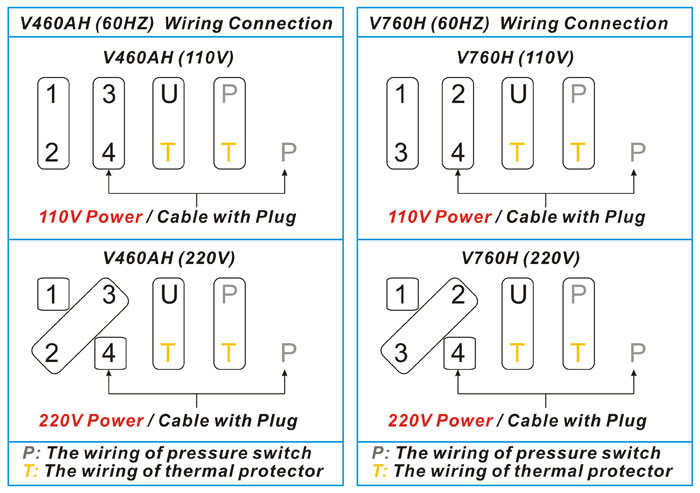
well pump pressure switch wiring diagram - You will need a comprehensive, expert, and easy to comprehend Wiring Diagram. With this kind of an illustrative guide, you are going to be able to troubleshoot, prevent, and complete your assignments with ease. Input Vol. 380V connect pump C.Wiring diagram of stable pressure Input.Vol380V WaterPump Controller Note: Please make sure switch 'Pressure /Liquid level' to 'Pressure', and switch 'w ate rfilli n g/ t edrai o Wat r filling'. The motor starts while pressure drops to min. pressure contactor, stops while pressure rise to max. pressure
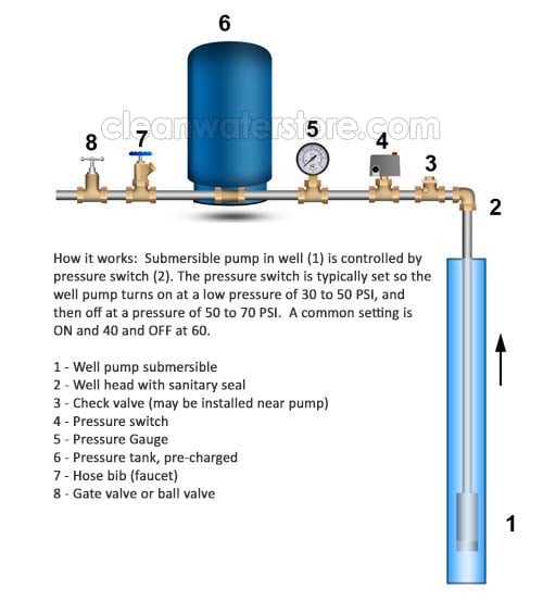
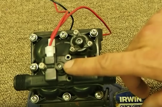
If you have a private well water system, your Pressure Switch is an integral component. The Pressure Switch tells the pump that delivers water to your home when to turn on and off. When the pressure in the system drops to a preset low setting the pump will turn on (commonly known as the cut-on pressure).

Water pump pressure switch diagram
water pump pressure switch wiring diagram - Architectural wiring layouts reveal the approximate areas and also interconnections of receptacles, lighting, and also long-term electric solutions in a building. Interconnecting cable paths could be revealed about, where specific receptacles or fixtures must get on a typical circuit. ... 11. Pressure Gauge Measures water pressure in Pressure Tank. 12. Pressure Switch Signals the pump to start when the water system drops to a pre-set low pressure, and to stop when the high-pressure mark is reached. 13. Safety Switch For electric control and distribution to the pump. 14. Pump Saver Adjustable, solid control monitors system load ... If this procedure or the wiring diagrams are. Water pressure switches in well systems control the amount of water pumped to the system's storage tank. As the tank is filled, the water pressure increases within it. How to Wire Up a Well Water Pressure Switch By Max Stout. Connect the white wire from the well pump to the T2 terminal on the ...
Water pump pressure switch diagram. How to install or replace a water pump pressure control private and well system do it yourself repairs switch wiring terry love plumbing advice remodel diy professional forum wire installation guide questions doityourself com community forums three 120v directly into i am rewiring can you help me with the diagram 220 step by troubleshooting repair diagrams table 110… Read More » Pressure control switch replacement procedure: Water pump switch replacement: this article describes how to replace a water pressure control switch which is not working properly or perhaps is not working at all. We describe and illustrate how to find the pump switch, then we detail how to identify, remove, and replace the water pump pressure control switch for both above-ground pump and ... Well Pump Pressure Switch Wiring Diagram Collection. Collection of well pump pressure switch wiring diagram. A wiring diagram is a simplified traditional photographic representation of an electric circuit. It reveals the parts of the circuit as simplified forms, and the power as well as signal connections between the tools. A wiring diagram usually gives info concerning the… Referring to the diagram, we can see 3 identical stages wherein 3 pressure switches are configured with 3 associated relay driver stages, and the relay contacts attached with the respective 3 water pumps.. In the relay driver stage we have used a PNP transistor because the pressure switch response is normally switched OFF during low pressure and ON when the pressure reaches the maximum ...
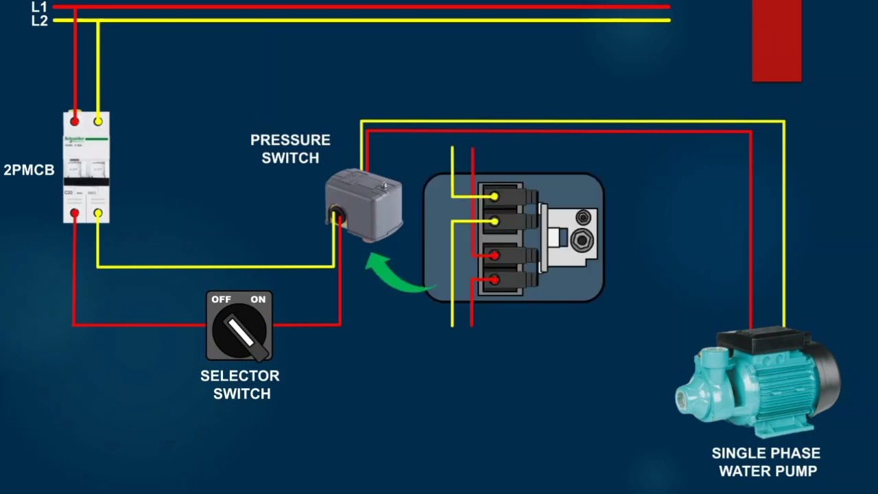
Basically, you will find 2 types of wiring diagrams for a well pump pressure switch. One is the 2 wire pressure switch, and another is a 3-wire pressure switch. And after checking out some pressure switch connection diagram s, we can say that the 220v well pump wiring switch primarily uses the 2-wire submersible pump. Closes the contacts on rising air or water pressure designed to ground ignition on gas driven pumps and compressors. Can also act as a low pressure alarm or to prevent pump operation at low pressure. Reset lever optional. Hi-Gard-69WH Wired in series with a standard switch. Designed to cut-out when a preset pressure is reached. Hi-Gard is used ... 21.8 psi model - max. system pressure generated by pump must be at least 33.4 psi, column of water between the unit and the highest tap must not exceed 50 ft. 31.9 psi model - max. system pressure generated by pump must be at least 43.5 psi , column of water Float Switch Connection Single Phase Water Pumpwhat is float switch?float switch is a type of level sensor a device used to detect the level of liquid within...
DOWNLOAD. Wiring Diagram Pictures Detail: Name: water pump pressure switch wiring diagram - Well Pump Pressure Switch Wiring Diagram Exquisite Stain Psidekick Install And. File Type: JPG. Source: teenwolfonline.org. Size: 90.88 KB. Dimension: 598 x 366. DOWNLOAD. Wiring Diagram Sheets Detail: In this video, we show you the best way to a pressure switch for 115V and 230V pumps. This method will work for any pump that runs directly off of a pressure... Water Pump Wiring Troubleshooting Repair Diagrams. Water pump wiring troubleshooting well installation guide how to wire a 220 pressure switch submersible diagrams 240 volt diagram three 120v i am rewiring can you help directly generator typical 220v stenner 4 110volt electrical stainless steel please franklin electric 3 vs hallmark industries inc goulds control box for 1 5hp munro companies ... Pressure switches are used on water pumps for the accurate control of the Switch off the power that feeds the pump circuit while you are wiring the switch. May 10, To increase the cut-off and cut-on pressure, turn nut #1 clockwise. The rate of increase is 2 1/2 PSI for every complete turn of the nut. Do not.Merrill Manufacturing is the leader ...
Buy Lefoo Lf5510 Adjustable Hvac Pressure Control Steam Boiler Pressure Switch Single Refrigeration Air Water Pump Compressor Pressure Switch 14 5 Psi 145psi Online In Indonesia B07q6wbncv
Pressure Switch Pump Pressure Switch Ground Wire (Green) 4 in. Min. Well ID Breaker Box HOW MANY WIRES DOES YOUR EXISTING PUMP INCLUDE? Wiring Diagram for pumps with 2 wires plus ground Switch 10 20 30 40 50 60 70 80 Tank Control Box To Pressure To Control Box Pump Pressure Switch Ground Wire (Green) 4 in. Min. Well ID Breaker Box To Pump ...
How To Adjust The Pressure Psi On Your Pressure Switch 12v Faq Water Pumps Now Free Shipping
Water Pump Pressure Switch Wiring Diagram. Variety of water pump pressure switch wiring diagram. A wiring diagram is a streamlined standard photographic depiction of an electric circuit. It reveals the elements of the circuit as streamlined forms, as well as the power and also signal connections in between the devices. A wiring diagram typically gives information…
How To Set Up A Pump Station Relay Water Pressure Switch For Pump Types Installation Adjustment
How to set the pump pressure control switch: Starting here with advice about correct problem diagnosis of water pressure problems, this article series describes how to adjust building water pressure by setting the water pump cut-in and cut-out pressure on the well water pump pressure control switch.. In brief tutorials we explain how to set and adjust a typical pump pressure control switch ...
Booster Pump Installation Instructions Pure Water Products Llc
Water Pump Pressure Switch Wiring Diagram - square d water pump pressure switch wiring diagram, water pump pressure control switch wiring diagram, water pump pressure switch wiring diagram, Every electrical structure is composed of various different components. Each part should be placed and connected with other parts in particular way. Otherwise, the structure won't work as it should be.

Buy Electronic G1 2 Pressure Control Switch Air Water Pump Pressure Controller At Affordable Prices Free Shipping Real Reviews With Photos Joom
Diagrams --Typical Pump Installations. The information provided here is for educational purposes only. Technically qualified personnel should install pumps and motors. We recommend that a licensed contractor install all new systems and replace existing pumps and motors. Failure to install in compliance with local and national codes and ...
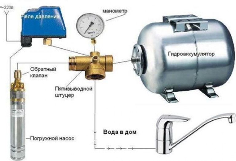
Connection Diagram Of A Water Pressure Regulator From A Well Correct Connection Of The Water Pressure Switch To The Submersible Water Intake Pump
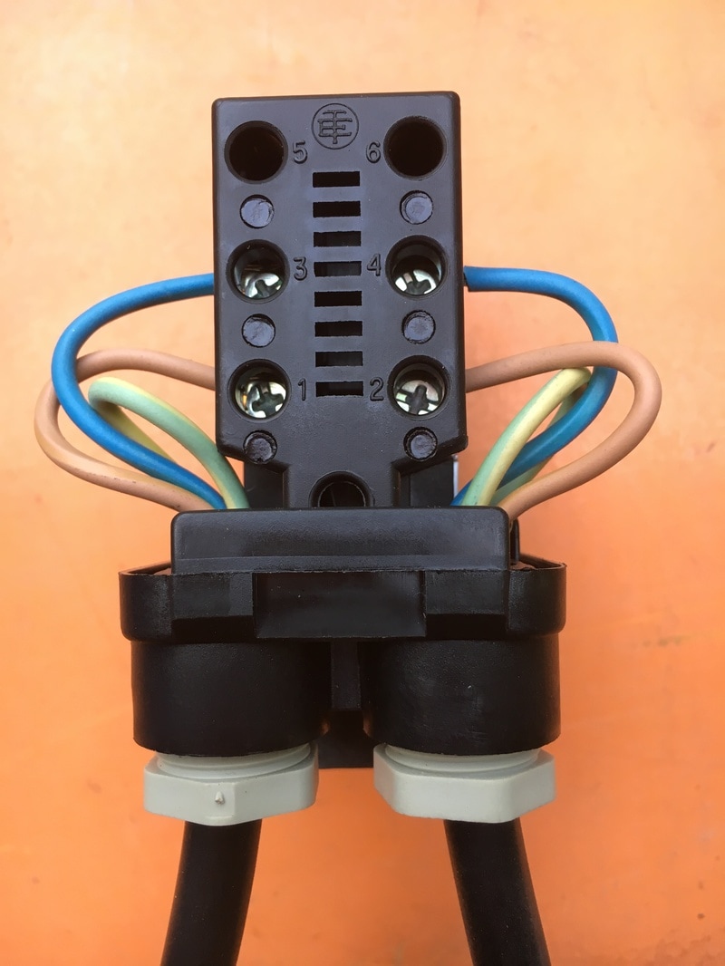
The Pressure Switch is a "Pumptrol FSG2J21M4" (Has the additional "lever") The new switch is in position on the tank, but I am confused as to the wiring configuration. The orange card that came with the part shows a diagram that indicates "T1" and "T2" and "L1" and "L2". A Square D pressure switch is a means of controlling pressure in a pump.

Water Pump Pressure Control Switch Electronic Pressure Controller For Air Water Compressor Buy At A Low Prices On Joom E Commerce Platform
Shurflo Water Pump Wiring Diagram - rv water pump switch wiring diagram, rv water pump wiring diagram, shurflo 12v water pump wiring diagram, Every electric arrangement consists of various unique components. Each part should be placed and connected with other parts in particular way. If not, the structure won't work as it should be.
Pressure Switch Adjustment Water Bore Pump Submersible Bore Pumps
Wiring Diagram for Well Pump Pressure Switch- wiring diagram is a simplified suitable pictorial representation of an electrical circuit.It shows the components of the circuit as simplified shapes, and the capacity and signal friends in the middle of the devices.

Tech Topics Tips Simplify Water Well Pump Control Circuits Setup 2014 01 01 The Driller
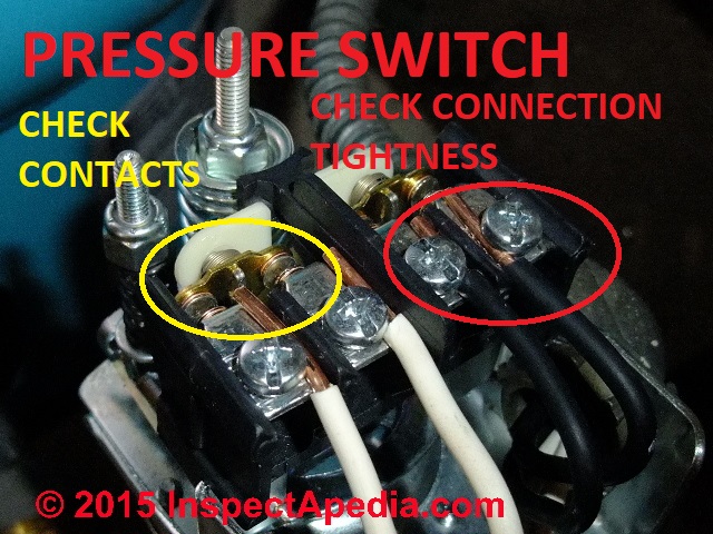
Continuous tripping could be caused by a broken wire leading to or inside the water pump. Check the well tank pressure gauge to see if it is at least 40 PSI (or the cut-off PSI for your pressure switch model). If it isn't, make sure your filter isn't clogged or in need of a change. Check the pressure gauge to make sure it isn't stuck or ...
2017 Monro Square D Pressure Switch For Water Pump Krs 3 Black Cover View Square D Pressure Switch Monro Product Details From Zhejiang Monro M E Co Ltd On Alibaba Com
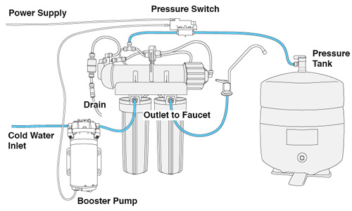
Booster Pump Installation Instructions 1. Install pressure switch in tank line. (See diagram on back for where to place the pressure switch). 2. Pump must be located within 2 feet of pressure switch and within 6 feet of power outlet. A. Pump can be mounted to the wall horizontally in either direction or vertically only one way ~ with pump head and

How Variable Speed Pumps Pressure Sensors Can Improve Water Systems Wqp
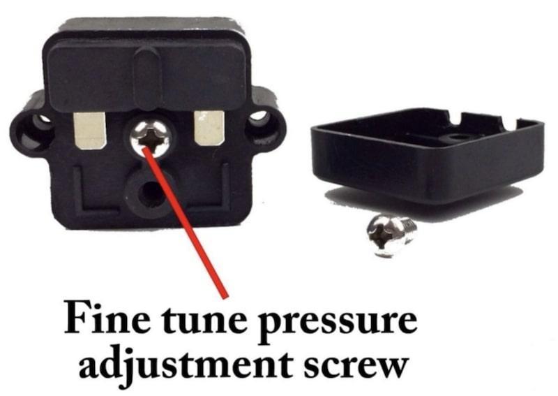
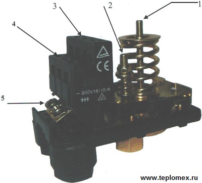
This pressure switch signals the pump to start when the water system drops to 30 installing the switch, hold the lever in the start position until pressure reaches. To increase the cut-off and cut-on pressure, turn nut #1 clockwise. The rate of increase is 2 1/2 PSI for every complete turn of the nut. Do not.

220v G 1 4 Inch Female Threaded Water Pump Pressure Switch Controller Mechanical Action 1 0 1 8 1 5 2 2 1 8 2 6 2 2 3 0kgf Cm2 Buy At The Price Of 9 20 In Aliexpress Com Imall Com
If this procedure or the wiring diagrams are. Water pressure switches in well systems control the amount of water pumped to the system's storage tank. As the tank is filled, the water pressure increases within it. How to Wire Up a Well Water Pressure Switch By Max Stout. Connect the white wire from the well pump to the T2 terminal on the ...
1
11. Pressure Gauge Measures water pressure in Pressure Tank. 12. Pressure Switch Signals the pump to start when the water system drops to a pre-set low pressure, and to stop when the high-pressure mark is reached. 13. Safety Switch For electric control and distribution to the pump. 14. Pump Saver Adjustable, solid control monitors system load ...

On 1 5bar Off 10bar Automatic Water Pressure Switch Controller For Water Pump Plumbing Fixtures Tipidkorpolri Home Garden
water pump pressure switch wiring diagram - Architectural wiring layouts reveal the approximate areas and also interconnections of receptacles, lighting, and also long-term electric solutions in a building. Interconnecting cable paths could be revealed about, where specific receptacles or fixtures must get on a typical circuit. ...
How To Determine Your Well Pump Flow Rate On Wells With Pressure Tanks Residential Well Water Treatment Iron Filters Acid Neutralizers Chlorinators
Pengontrol Pompa Tekanan Pompa Air Pintar Epc 1 Sakelar Elektronik Aliran Otomatis Buy Cerdas Saklar Tekanan Pompa Pompa Air Controller Secara Otomatis Aliran Saklar Elektronik Aliran Elektronik Switch Saklar Tekanan Pompa Air Product On Alibaba Com
How To Adjust The Pressure Switch On A Shurflo Water Pump
How To Install Or Replace A Water Pump Pressure Control Private Pump And Well System Do It Yourself Repairs
Pressure Switch Adjustment Water Bore Pump Submersible Bore Pumps

Pressure Switch Faqs

How To Wire A Well Pump To The House Kobo Guide

Shut It Off Turning Off And On A Well Water Source You Don T Need A Man To Fix It

Scorpio Pressure Control Switch For Well Tank Water Pump Double Spring 7453078504278 Ebay
Electronic Automatic Pump Controller Water Pump Automatic Pressure Switch Pressure Control Buy Electronic Automatic Pump Controller Water Pump Automatic Pressure Switch Pressure Control Automatic Pressure Control Switch For Water Pump Pressure Swith
V Series Auto Booster Pumps Welcome To Evergush Pump Genset Official Website Professional Water Pump Diesel Genset Manufacturer From Taiwan Taiwan Pump

How To Adjust Pressure Switch On Well Pump Arxiusarquitectura

Buy Solimeta Adjustable Air Pump Pressure Switch 1 4npt Female 40 60 Psi Pressure Setting Pressure Switch For Water Pump Well Pressure Switch Pump Pressure Switch Online In New Zealand B08f4crlyy

Aim Manual Page 56 Single Phase Motors And Controls Motor Maintenance North America Water Franklin Electric

China 2020 New Water Pump Pressure Controller With Pressure Adjustment Function China Switch Control Pump Protection Pump Controllers

Square D By Griven Italy Pressure Control Switch For Well Tank Water Pump 11 95 Picclick

Tech Topics Tips Simplify Water Well Pump Control Circuits Setup 2014 01 01 The Driller
Water Pump Controlled By Pressure Switch Single Phase Motor Youtube

How A Well Pressure Tank Works With Diagrams Plumbing Sniper

Wiring Diagram For 220 Volt Submersible Pump Bookingritzcarlton Info In 2021 Well Pump Pressure Switch Submersible Well Pump Well Pump

Lefoo Pressure Switch Lf55 Automatic Pressure Control Manual Reset Pressure Switch For Havc Electronic Water Pressure Control Switch Water Pump Pressure Switch Zhejiang Lefoo Controls Co Ltd Pdf Catalogs Technical Documentation Brochure
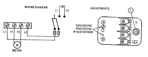
Figure 6 Water Pump Wiring Diagram

Please Log In Well Pump Repair Well Pump Submersible Well Pump

China Electronic Pump Controller To Control Water Pump Pressure China Pump Controller Pump Control
Pressure Switch Wiring Terry Love Plumbing Advice Remodel Diy Professional Forum

220v Automatic Water Pump Pressure Controller Electric Electronic Switch Control Unit Buy Online In Togo At Togo Desertcart Com Productid 19645378
0 Response to "40 water pump pressure switch diagram"
Post a Comment