44 pressure sensor circuit diagram
Arduino BMP Sensor Tutorial - How BMP Sensor Works and ... The Schematic Diagram of the BMP280 Temperature and Pressure Sensor is shown below and as you can see it's very simple to understand. The BMP280 has two separate power supply pins VDD is the main power supply for all internal analog and digital functional blocks and VDDIO is a separate power supply pin, used for the supply of the digital interface. Pressure Sensor - Electronic Circuit Diagram This is pressure sensor signal conditioning circuit. It is simple and inexpensive circuit because it has small geometry and simple pressure sensor. It just uses a single Operational Amplifier. This circuit obtain power from from 3-V battery. To work properly this circuit must work in 0 C to 50 C temperature range.
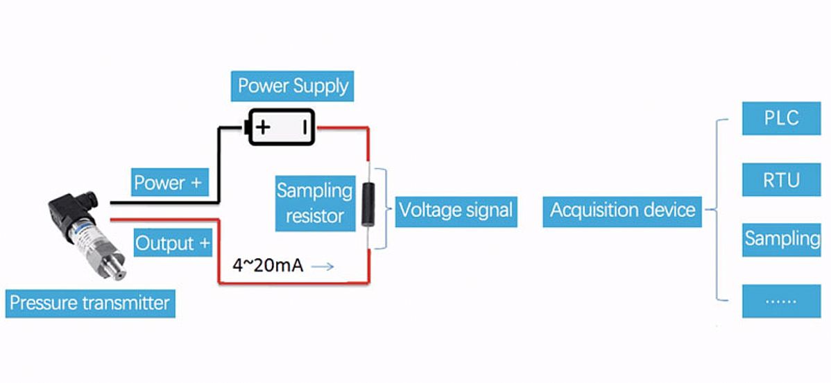
Pressure sensor - no wiring diagram - Sensors - Arduino Forum If the sensor has two wires, 4-20 mA output, the standard way to read it with Arduino is to use a 250 Ohm series resistor, and read the voltage drop across the resistor. 4 mA = 1V, 20 mA = 5V. The sensor power supply can be anywhere between 12 and 36 V, but 9V may work.
Pressure sensor circuit diagram
› light-sensor-circuitLight Sensor - Circuit Diagram, Working and Its Applications Jan 07, 2021 · Light Sensor Circuit Working Operation. The light sensor circuit is an electronic circuit designed using (light sensor) LDR, Darlington pair, relay, diode, and resistors which are connected as shown in the light sensor circuit diagram. A 230v AC supply is provided to the load (in this case, the load is represented with a lamp). › logging-arduino-data-toHow to Write Arduino Sensor Data to a CSV ... - Circuit Basics Dec 29, 2014 · In this tutorial, we are going to connect a BMP280 barometric pressure sensor to an Arduino and write the results to a computer using a terminal emulator called PuTTY. The BMP280 will be connected using I 2 C. We will collect data and write to file a make-shift timestamp by reading the elapsed time since the Arduino started. › p0090P0090 Fuel Pressure Regulator 1 Control Circuit Open P0091 Fuel Pressure Regulator 1 Control Circuit Low; P0092 Fuel Pressure Regulator 1 Control Circuit High; Symptoms & Severity. Excessive fuel pressure can lead to a variety of drivability issues, as well as causing internal engine and catalytic converter damage. For this reason a code P0090 should be classified as severe.
Pressure sensor circuit diagram. create.arduino.cc › projecthub › sarfulDigital Pressure Sensor– Arduino Workshop - Arduino Project Hub In this project, we are going to Digital Pressure Sensor– Arduino and learn how to use an MPL3115A2 pressure sensor, the MPL3115A2 digital pressure sensor from Freescale. This is a great sensor that is easily interfaced with an Arduino and provides accurate pressure and temperature readings. Pressure Transducers |Installation and Wiring Diagrams Apply pressure to the transducer using a handheld pump. Watch to ensure the pressure changs on all three units. Verify, once the pressure is steady and static, that all three units are displaying the same pressure readout. You can use this process to set up a system that will log, record, and graph the pressure transducer's data. Pressure Sensors | The Design Engineer's Guide | Avnet Abacus An absolute pressure sensor may be designed to respond to pressure applied at the top side or the back side, when mounted on a circuit board or a panel, for example. Creating a port for the measured media to enter through the top side may leave the sensor vulnerable to hazards such as physical damage or contamination with dirt or moisture. Faults and solutions for current loop ... - Pressure Sensor Check whether the wiring is loose or not which causes the contact resistance to increase. It is equivalent to the load increase. Check whether the actual pressure exceeds the selected range of the pressure transmitter. Change a pressure transmitter with an appropriate range. Check whether the pressure sensor is damaged.
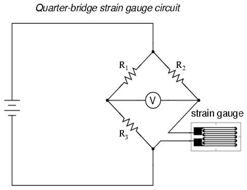
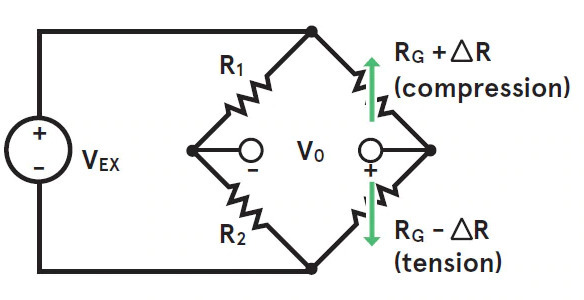
pressure sensor circuit diagram - Gallery 4K Pressure Sensor Circuit Diagram. Pressure sensor circuit without using alarm schematic diagram of simplified electrical sensors the design engineer optical working diffeial simple amplifier over electronic demystifying piezoresistive. Pressure Sensor Circuit Without Using Microcontroller Gadgetronicx. GY-BMP280-3.3 Pressure Sensor Module Arduino Tutorial Below is the wiring diagram as described above. Arduino Due GY-BMP280-3.3 Pressure Sensor Module I²C Wiring Diagram I²C Wiring to 5V Arduino Uno. A bidirectional level shifter module can be used to connect the 3.3V GY-BMP280-3.3 module I²C pins to a 5V Arduino such as an Arduino Uno or Arduino MEGA. PDF MPXV7002, Integrated silicon pressure sensor, on-chip ... Integrated silicon pressure sensor, on-chip signal conditioned, temperature compensated and calibrated ... Figure 1 shows a block diagram of the internal circuitry integrated on a pressure sensor ... Figure 6 shows the recommended decoupling circuit for interfacing the integrated sensor to the analog-to-digital input of a microprocessor or ... Pressure Transducer : Circuit Diagram, Types and Its ... This conversion process can be done with the strain gage's physical deformation that is connected into the pressure transducer's diaphragm & wired in the design of a Wheatstone bridge. Once the pressure is applied to this transducer, then it generates the diaphragm deflection.
PDF Pressure sensors: The design engineer's guide The worldwide pressure sensor market was worth $7.1 billion USD in 2015 and is estimated to be worth $11.4 billion by 2024. That's 60% growth over 6 years or a compound annual growth rate of 5.4%. And while analysts are busy predicting the future, engineers are busy creating it. In recent years, pressure sensors have become Pressure Sensor & Wiring Diagram - YouTube Get the scoop here on pressure sensors. They're used in injection systems, transmission, HVAC and many other systems. Presented using advanced software CG animation technology to help you... 3 & 4 Pin MAP Sensor Wiring Diagram - Easy Car Electrics 4 Wire MAP Sensor Wiring Diagram A four-wire manifold absolute pressure sensor has the following four wires. 12 Volt Feed Positive Power Wire Ground Wire MAP Signal Wire Intake Air Temperature (IAT) Sensor Signal Wire A 4 wire manifold absolute pressure sensor has a 5-volt reference voltage, which is connected to the car computer (ECU). Pressure Sensor Alarm Circuit Schematic Whenever, the pressure sensor element (Piezo-ceramic wafer) is gently tapped, mosfet T1 is fired by the electric pulse from the sensor through related components and IC1 is again enabled by T1. As a result, the piezo-sounder starts beeping for a short duration, set by the in-circuit values of R3 and C2.
Pressure Sensor – Electronic Circuit Diagram
Pressure Sensor Circuit Diagram | Technology Talk | TechTalk Pressure Sensor Circuit Diagram February 18, 2021 admin Pressure Sensor This sensor is based on the Lucas NovaSensor NPC-410 Series pressure sensor. The circuit below contains the usually powered sensor interface, but I used an LM358 dual opamp in place of the usual LM324. The 78L05 regulates the voltage from the RCX down to 5V.
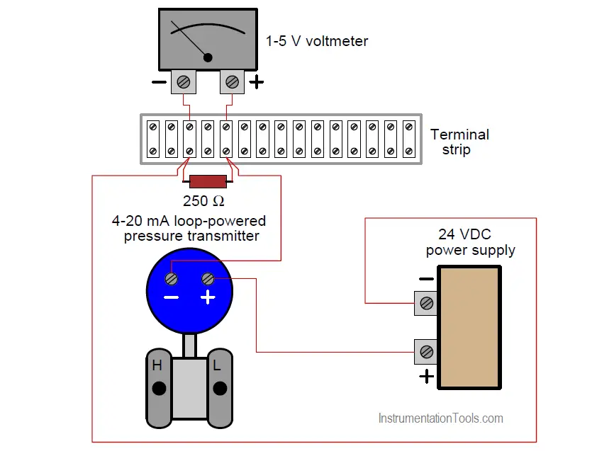
Pressure Transmitter Circuit - InstrumentationTools
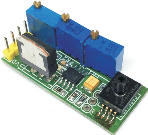
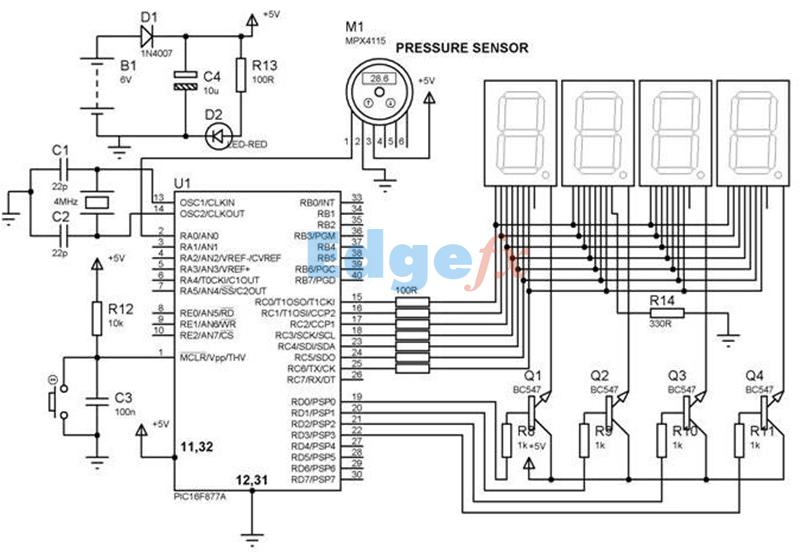
Pressure sensor circuit without using Microcontroller ... 12v & 6v power source WORKING OF PRESSURE SENSOR CIRCUIT: The working of this circuit starts with Piezoelectric transducer element which is used as Pressure sensing element in our circuit. Piezo sensors generate voltage when pressure is applied on its surface. When there's no pressure input applied to the Piezo element the output will be 1/2 Vcc.
Blood pressure sensing circuit diagram BP01-type pressure ...
Pressure Detector Circuits and Block Diagram Basics Within the block / circuit diagram illustrated below, the sensing element senses the pressure of the monitored system and converts the pressure to a mechanical signal. The sensing element supplies the mechanical signal to a transducer, as discussed above. The transducer converts the mechanical signal to an electrical signal that is proportional to system pressure.

Oil Pressure Sensor Circuit Hotsell, 53% OFF | www.emanagreen.com
Interfacing SPD005G Pressure Sensor To Arduino-Circuit ... The full circuit diagram for interfacing pressure sensor to arduino is given below. Circuit diagram. An instrumentation amplifier based on quad opamp LM324 is used for conditioning the output voltage from the pressure sensor.The instrumentation amplifier amplifies the differential voltage between output pin 4 and 1 of the pressure sensor.
The circuit diagram of a blood pressure device for | Chegg.com
› blog › p0138-code-o2-sensorP0138 Code: O2 Sensor Circuit High Voltage (Bank 1, Sensor 2 ... Jun 23, 2021 · Diagnostic trouble code (DTC) P0138 stands for O2 Sensor Circuit High Voltage (Bank 1, Sensor 2). The code will set when your car’s primary computer—also called the powertrain control module (PCM)—detects that, for a given period of time, the voltage signal from the rear O2 sensor is too high.

p0237-turbo boost pressure sensor circuit low
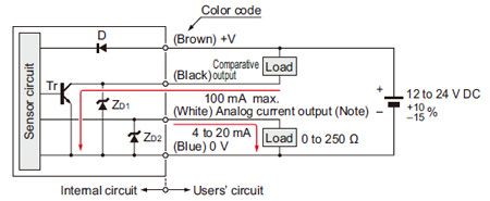
Electr. circuit for pressure sensors (active ... - WIKA blog Electrical circuit for pressure sensors: when is a sensor active, and when passive? When using pressure sensors, the output signals 0 … 20 mA, 4 … 20 mA and DC 0 … 10 V are frequently chosen in order for the sensor signals to be evaluated and further processed.

Absolute Pressure Sensors | The Design Engineer's Guide ...
PDF MPM4841 Pressure Sensor Brief Introduction MPM4841 pressure transmitter uses a high-stability, high reliability piezoresistive pressure sensing element and a special conditioning circuit to output a standard current or voltage signal. It is compact in size, excellent in quality, stable and reliable in overall performance.

Pressure Sensor & Wiring Diagram
› p0090P0090 Fuel Pressure Regulator 1 Control Circuit Open P0091 Fuel Pressure Regulator 1 Control Circuit Low; P0092 Fuel Pressure Regulator 1 Control Circuit High; Symptoms & Severity. Excessive fuel pressure can lead to a variety of drivability issues, as well as causing internal engine and catalytic converter damage. For this reason a code P0090 should be classified as severe.
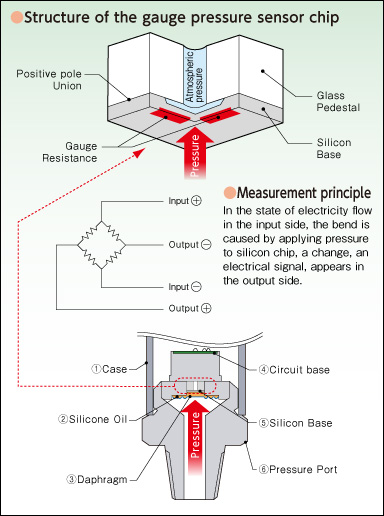
Structural Schematics for Pressure Sensors | VALCOM CO.,LTD ...
› logging-arduino-data-toHow to Write Arduino Sensor Data to a CSV ... - Circuit Basics Dec 29, 2014 · In this tutorial, we are going to connect a BMP280 barometric pressure sensor to an Arduino and write the results to a computer using a terminal emulator called PuTTY. The BMP280 will be connected using I 2 C. We will collect data and write to file a make-shift timestamp by reading the elapsed time since the Arduino started.

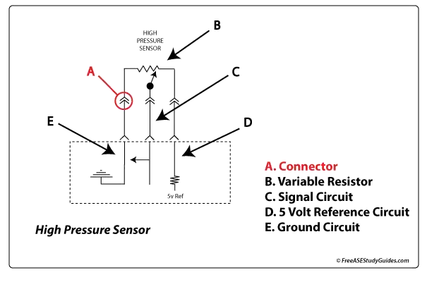
High Pressure Sensor Circuit Question and Answer
› light-sensor-circuitLight Sensor - Circuit Diagram, Working and Its Applications Jan 07, 2021 · Light Sensor Circuit Working Operation. The light sensor circuit is an electronic circuit designed using (light sensor) LDR, Darlington pair, relay, diode, and resistors which are connected as shown in the light sensor circuit diagram. A 230v AC supply is provided to the load (in this case, the load is represented with a lamp).
A/C Pressure Sensor Function

FSR Velostat pressure sensor circuit with LM324 opamp ...

Pressure Sensors
Faults and solutions for current loop transmitters
Pressure Sensors
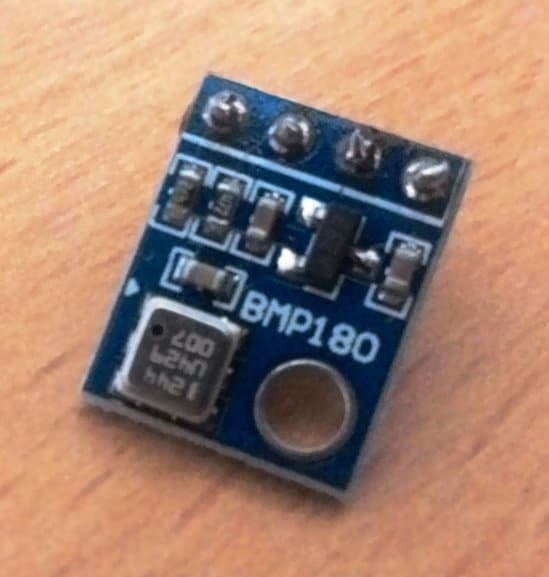
Interfacing Pressure Sensor BMP180 with Arduino Uno
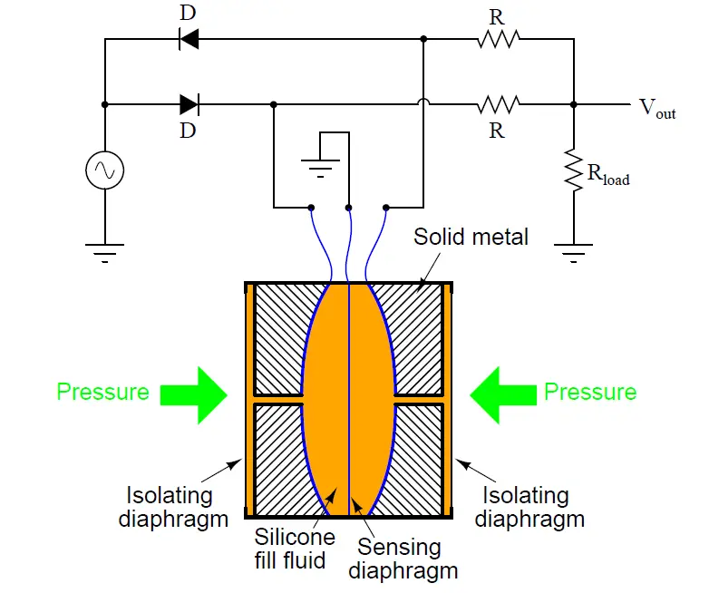
Differential Capacitance Pressure Sensor Circuit

Arduino Pressure Sensor Tutorial | MPS20N0040D
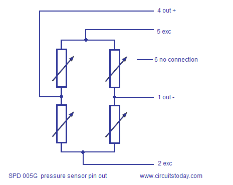
Interfacing SPD005G Pressure Sensor To Arduino-Circuit ...

MPS020N0040D Sensor as a Pressure Activated Switch – Arduino++

Pressure Sensor Circuit - advice/critiques appreciated! | All ...
Force / Pressure switch circuit using FSR - Gadgetronicx

Circuit Diagram of Pressure Sensor | Download Scientific Diagram
Micro-differential Pressure High-precision Digital Pressure ...

2SMPP MEMS Gauge Pressure Sensor - Omron Electronics | Mouser

Simplified electrical circuit diagram of a piezoresistive ...
Simple Pressure Sensor Amplifier & Over Pressure Switch ...

Tilt Sensor Alarm Circuit

Figure 1 from Differential Wide Temperature Range CMOS ...
Sensor Basics: Types and List of Sensor Based Latest Applications

filter - Suppressing interference in a pressure sensor ...
A Simple Pressure Sensor Signal Conditioning Circuit
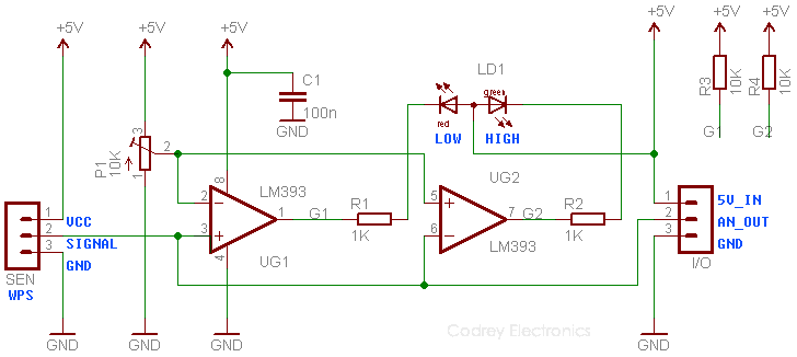
How to Play with a Water Pressure Sensor? - Codrey Electronics
Barometric Pressure Sensor Circuit - Working and Interfacing ...

Sensors | Free Full-Text | Passive Resistor Temperature ...
Digitizing Facial Movement During Singing

Optical Pressure Sensor-Working,Construction,Circuit Diagram
Types of Pressure Sensor - A Guide

Pressure Sensor Alarm
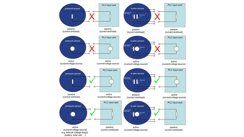
Electr. circuit for pressure sensors (active/passive) - WIKA blog
Pressure Transducer Sensor | How it works | FUTEK
Installing a Tire Pressure Monitoring System - Industry Articles
MAP sensor

Gauge Pressure Sensors | The Design Engineer's Guide | Avnet ...
0 Response to "44 pressure sensor circuit diagram"
Post a Comment