41 4 in 1 esc wiring diagram
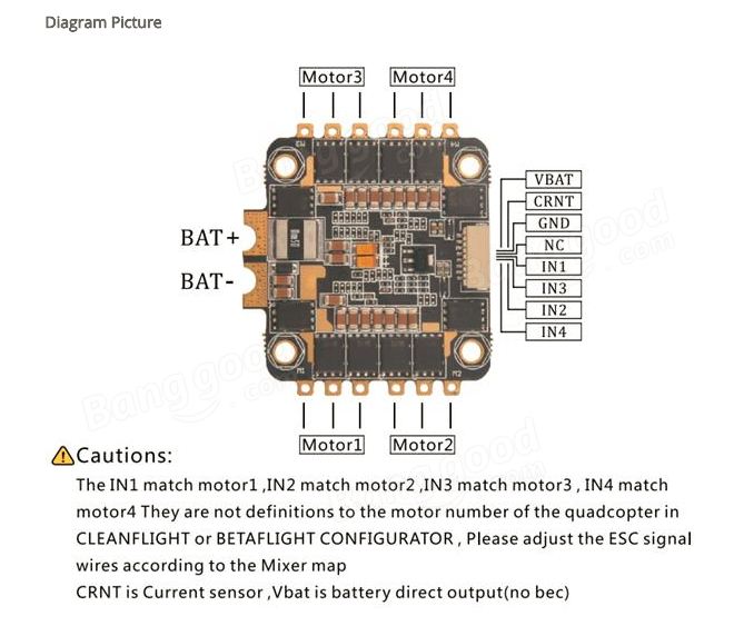
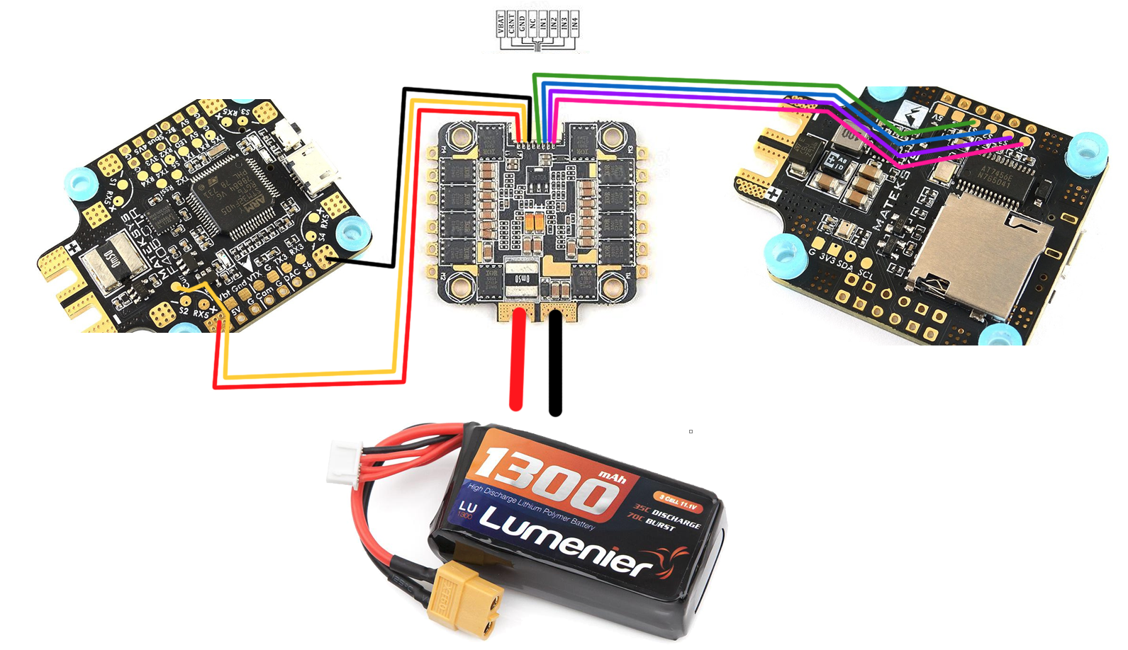
How To Connect Quadcopter Motors and ESC - DroneTrest To connect the ESC to your flight controller, most 4in1 ESC uses a connector to make wiring neater. The pinout labelling for the connector is usually included with the manual. In this example, the first 4 pins on the connector are for motors 4-1. NC stands for not connected. GND is for the ground connection to your flight controller. Lumenier 35A 4-in-1 ESC to CLRacing F4s JST Wiring Diagram ... The current sensor has to be in series with the load to measure it. So to use the current sensor on the FC you need to connect the battery straight to it and then ESCs to the FC. With a 4-in-1 ESC it might be more convenient to put the sensor there. EDIT: At least shunt resistor current sensing, which is what I always see on FCs and ESCs. 4 level 2
flight controller - Wiring a 4-in-1 ESC to an Arduino Uno ... Wiring a 4-in-1 ESC to an Arduino Uno. Ask Question Asked 1 year, 2 months ago. Modified 1 year, 2 months ago. Viewed 652 times 6 1 $\begingroup$ I have four brushless motors that I want to control using an Arduino Nano. I was looking at getting a 4-in-1 ESC controller similar to this one on amazon. At this point in my project, I'm more ...

4 in 1 esc wiring diagram
ESC wiring and connections - KISS documentation ESC wiring and connections. KISS ESC 25A 4-in-1 wiring. Wiring Diagram. 1. BLDC Motor phases (3) 2. Lipo Power Supply +. 3. Lipo Power Supply - (GND) XRotor FPV Stack (4in1 ESC & FC ) - HOBBYWING North America Combo deal to save more $ p/n Value 38040303 Combo 40A Micro 4in1 ESC & F7 Flight Controller $167 38040304 Combo 60A Micro 4in1 ESC & F7 Flight Controller $180 38040028 Combo Nano 4in1 ESC&FC $88 Related products Xrotor 4in1 Micro / Nano ESC system Xrotor F7 Flight Controller system Video (VTX) Azure Pow Pixhawk 4 Mini Wiring Quickstart · PX4 v1.9.0 User Guide JST-GH 6-pin Connector, 5V 3A output. connect to Pixhawk 4 Mini POWER. BAT. Power Input, connect to 2~12s LiPo Battery. The pinout of the Pixhawk 4 Mini POWER port is shown below. The CURRENT signal should carry an analog voltage from 0-3.3V for 0-120A as default. The VOLTAGE signal should carry an analog voltage from 0-3.3V for 0-60V as default.
4 in 1 esc wiring diagram. (EOL)Flight Controller F722-SE - Matek Systems 4x RX6 pad (one per cornet) for BLheli32 ESC telemetry 4x individual ESC power/signal pads 1x Group of G/S1/S2/S3/S4 pads for 4in1 ESC Signal/GND 3x LEDs for FC STATUS (Blue, Green) and 3.3V indicator (Red) Vbat filtered output power for VTX, Switchable via AUX (modes tab-user1) Dual Camera image switchable via AUX (modes tab-user2) XILO Stax 45A BLHeli_32 3-6s 4-in-1 ESC - Wires Computing The XILO Stax 4-in-1 45A 3-6s ESC is plug n' play compatible and works seamlessly with the XILO Stax FC. The Stax 4-in-1 ESC continues XILO's tradition of giving you high-quality FPV gear for a low price point. And it couldn't be easier to install and use on your favorite airframe! Use this 4-in-1 ESC with the flight Fine Beautiful Low Voltage Transformer Wiring Diagram ... Low voltage transformer wiring diagram wiring diagram is a simplified adequate pictorial representation of an electrical circuit. In the left diagram below a 20 watt w bulb with a 120v source draws 16 amp. The e book features a large amount of sensible strategies for numerous situations that you might come across when you re dealing with wiring. Flip32-f3-omnibus Aio Asgard (f3+esc+osd+cs) Wiring Diagram Last edited by Ukalele94; Jan 31, at . Image result for F4 flight controller+4 in 1 ESC+FPV Transmitter wiring Asgard 4x25A Blheli_S / Asgard32 4x35A Blheli32 AIO - FC, 4in1 ESC PDB - Page 80 - RC Groups Omnibus F3 AIO quickstart guide - Guides - DroneTrest Diagram .
How to wire a 4 in 1 ESC - YouTube Today I hope to clear up any confusion I have created in wiring a 4 in 1 ESC to your motors and flight controller. All the stuffs I useTranis X9D Plus http:/... Ori32 4in1 Esc Wiring Diagram - schematron.org Use the correct wiring diagram from schematron.org Note: When using a Millivolt V2 , . Airbot Ori32 BLHeli32 25A 4-in-1 20x20 ESC (Includes breakout cables). 1. For bit 4in1 ESC that supports ESC Telemetry, there should be only 1 TX pin. You only need to connect this TX pin to a spare RX pin on the. 4. Connect ESCs and Motors — Copter documentation The Pixhawk should work with every ESC that works with a normal RC receiver (because it sends the same type of signal) but there is one known exception, the EMAX ESC. In most cases problems are due to incorrect wiring. Always connect signal and ground. Check your ESC type to decide how to connect the +5V line. SucceX 50A 2-6S BLHeli_32 Dshot600 4-in-1 ESC Package included: - 1 x SucceX 50A 2-6S BLHeli_32 Dshot600 4-in-1 ESC. Cody Ellis. 07/02/2020. The manufacturing is of good quality. It comes packaged in a small plastic box and includes mounting hardware, isolators, a 50v capacitor, wiring for ESC to FC and a nice XT60 pigtail. eloy duque. 07/02/2020. Just a great all around 4 in 1 ESC ...
4 in 1 ESC Wiring & Set Up - YouTube T-Motor F45A 3-6S BLHeli_32 4-in-1 ESC - GetFPV This ESC is T-Motor's 4-in-1 version of their popular F45A ESC. This 4-in-1 ESC packs 45A into an industrialized PCB layout made with premium features such as a 32bit main control chip, BLHeli_32 firmware, and 6s support. The F45A 4-in-1 comes with a heatsink attached to keep heat away from sensitive electronics. Wiring diagram - IntoFPV Forum Assuming you mean the T-Motor F55A Pro 4-in-1 ESC, using the white 10-pin and 8-pin ESC connectors on each board respectively, wire it in the following way. You can of course just solder directly to the pads with the same labels on the LUX F7 instead of using the white 8-pin connector if that is going to be easier. Amazon.com: AKK 30A 4 IN 1 2-6S Brushless ESC BLHeli_S ... For some reason on mine, motor I/O pins for motors 3 and 4 were swapped. Found the pins can be remapped in beta flight but this takes a little research to accomplish. My biggest complaint would be the lack of info for the ESC. No data sheet or wiring diagram is included, and the only wiring info I could find was from the Amazon listing ad itself.
4in1 esc with aio fc
Double check wiring diagram for new build : Multicopter Double check wiring diagram for new build. Just created this wiring diagram for my new build and mostly just have a question about wiring in regards to the 4 in 1 ESC and the motors. The FC and 4in1 are the XILO STAX F4 45A if it makes a difference. In this diagram the battery pads are pointed towards the back.
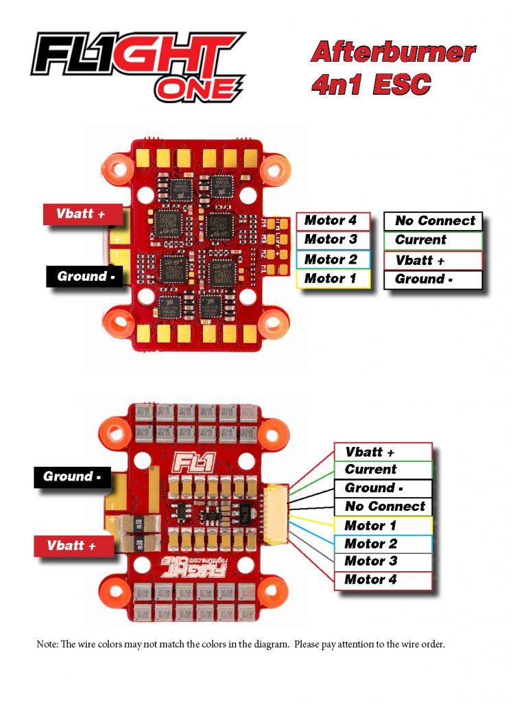
Afterburner ESC – FlightOne Support
PDF #11030 Kakute F4 (V2) - Holybro If your PDB or 4-in-1 ESC has a built-in analog current sensor, solder the 4thwire to the current sensor output on the PDB or ESC. Before proceeding with installation of your Kakute, you should complete as much of the PDB wiring as you can. For example, solder ESC power wires to your PDB. Solder the main XT60 plug to your PDB.
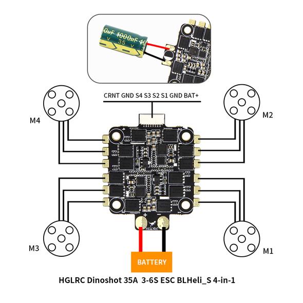
HGLRC DinoShot 35A 4-in-1 ESC
SucceX-E 45A 2-6S BLHeli_S Dshot600 4-in-1 ESC Package included: 1pc x SucceX-E 45A 2-6S BLHeli_S Dshot600 4-in-1 ESC. anteto. 21/07/2021. Very good ESC, powerful and good for the money. filip. 24/06/2021. Product supplied as advertised, promptly and in good order. gianns.
Pixhawk 2.4.8 with 4-in-1 esc - ArduCopter - ArduPilot Discourse
HOBBYWING XRotor User Manual - HOBBYWING North America High-light LED position light on the X-Rotor-50A ESC saves the trouble of mounting any extra color light on multi-rotors; The 4-in-1 dip switch at the bottom of the XRotor-50A ESC controls the ON/OFF status, color of the LED light, timing and the motor rotation. Specifications Throttle Calibration & ESC Programming

FPV Drone ESC Buyer's Guide - Oscar Liang
Electronic Speed Control (ESC) : Circuit, Types, Working ... As we know, an ESC controls the speed of the motor spin of an airplane. It helps a similar purpose as the throttle servo of a glow-powered airplane. It is an edge between the radio receiver of an airplane and the power plant. Electronic speed control will have 3- sets of wires. One wire will plug into the main battery of an airplane.

DYS F20A 4-in-1 ESC BLHeli_S Dshot
Omnibus f4 pro v3 + racerstar 4in1 ESC : Current Measure ... 4in1 ESC: Anniversary Special Edition Racerstar REV35 35A BLheli_S 3-6S 4 In 1 ESC Built-in Current Sensor for RC Drone Also I found this on some store's website: The wiring diagram that I see here is suggesting I connect the TX60's + to positive BAT+ of the FlightController, take one ESC V+ (from the FC) and connect that to the 4in1 ESC BAT+ ...

Lumenier BLHeli_S 20A 4-in-1 BEC 5V 1.5A ESC DSHOT
Hobbywing Xrotor Smart Audio Wiring Diagram FC/ESC Combo - Hobbywing XRotor Micro V2 Combo: F4 G2 FC and 45A BlHeli_32 4-in-1 Sever the excess wire with the wire cutters and strip the insulation with a penknife or a pair of wire strippers. Be sure to tin each wire before soldering it on to the 4-in - VTX 'Smart Audio' to FC 'UART6-Tx'. Omnibus F4 - Smart Audio with Unify Pro VTX
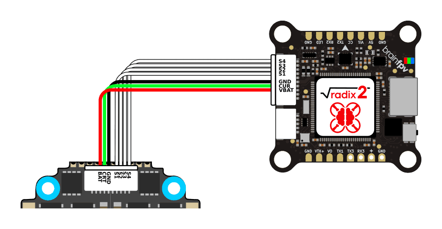
RADIX 2 4-in-1 ESC Connection - brainfpv
Review: Aikon AK32 4in1 35A ESC - Oscar Liang 1) You can use it to power your FC, or RX, VTX, Camera, LED etc if your FC doesn't have a big enough 5V regulator. 2) ESC telemetry is passed to the FC using a i2c protocol, the ESC telemetry data is sent to the FC with an unique ID header, and the FC can tell which ESC the data is coming from by checking this id.

Lumenier BLHeli_S 35A 4-in-1 12v / 5v BEC DSHOT ESC +Current ...
Matek F405 Ctr Wiring Diagram Matek F405 Ctr Wiring Diagram However, if you have a 4 in 1 ESC, the connection might get a bit confusing. Just follow the diagram below: The battery is connected to the ESC. The FCTR flight controller is the latest iteration of the popular F family from Matek matek fctr flight controller wiring and configuration diagram.

Racerstar REV35 35A BLheli_S 3-6S BB21 4in1 ESC w/ Current ...
Dji Phantom 4 Wiring Diagram Dji Phantom 4 Wiring Diagram. Prepare for your first flight by reviewing the Phantom 4 Pro / Pro+ Quick Start Guide and refer to the User Manual for more details. Watch the Tutorial Videos. Does anybody have any reliable wiring diagrams for the P3 Gimbal 8-pin cable, as well as the little one that comes from the VPS?.

HAKRC 35A 2-6S BLHeli_S 20x20 4-in-1 ESC
PDF 4in1 ESC 45A - FETtec Signal 1 - 4 have to be connected to the corresponding FC Motor outputs. The TLM wire has to be connected to an available serial TX pin. Configuration In order to utilize ESC provided current and voltage sensor the following settings need to be applied to Betaflight. (Feature, motor protocol and meter can be configured through the GUI itself).

Aikon Electronics
Racerstar 35a 4 In 1 Esc Wiring Diagram Wiring anniversary special edition racestar rev35a Anniversary Special Edition Racerstar REV35 35A BLheli_S S 4 In 1 ESC. FC goes to in 1 on your ESC, and the same for according to the diagram @stevieteeLumenier BLHeli_32 32bit 35A 4-in-1 ESC s w/ BEC 3A/12v, 1A/5v, DSHOT A 4 in 1 version of Lumenier's 35A Blheli_32 ESC.

Wiring a Matek F405 to DYS Aria D45A 4 in 1 ESC – flyingsquirrel
Pixhawk 4 Mini Wiring Quickstart · PX4 v1.9.0 User Guide JST-GH 6-pin Connector, 5V 3A output. connect to Pixhawk 4 Mini POWER. BAT. Power Input, connect to 2~12s LiPo Battery. The pinout of the Pixhawk 4 Mini POWER port is shown below. The CURRENT signal should carry an analog voltage from 0-3.3V for 0-120A as default. The VOLTAGE signal should carry an analog voltage from 0-3.3V for 0-60V as default.
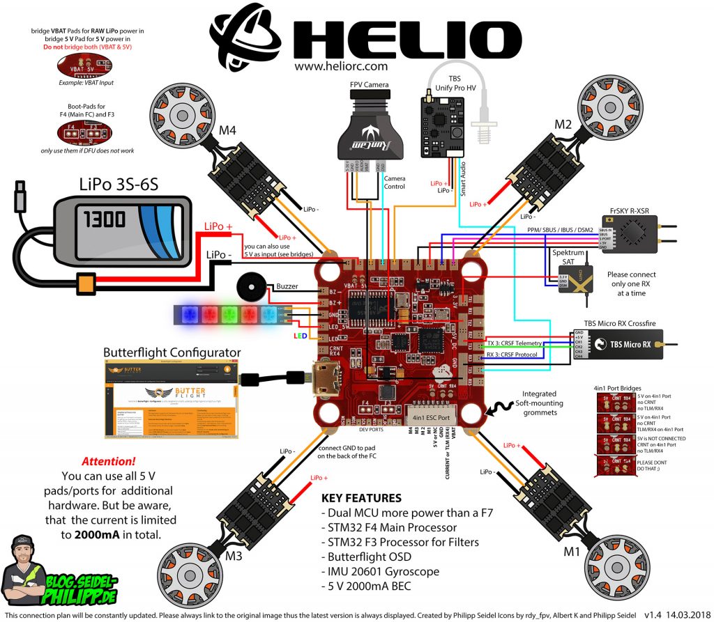
Helio RC Spring Flight Controller | GetFPV Learn
XRotor FPV Stack (4in1 ESC & FC ) - HOBBYWING North America Combo deal to save more $ p/n Value 38040303 Combo 40A Micro 4in1 ESC & F7 Flight Controller $167 38040304 Combo 60A Micro 4in1 ESC & F7 Flight Controller $180 38040028 Combo Nano 4in1 ESC&FC $88 Related products Xrotor 4in1 Micro / Nano ESC system Xrotor F7 Flight Controller system Video (VTX) Azure Pow
Configuring an ESC with BLHeli firmware using an Arduino Uno ...
ESC wiring and connections - KISS documentation ESC wiring and connections. KISS ESC 25A 4-in-1 wiring. Wiring Diagram. 1. BLDC Motor phases (3) 2. Lipo Power Supply +. 3. Lipo Power Supply - (GND)

HAKRC 4IN1 20A 15A BLheli_S ESC 2 4S for Mini F4 Flytower F3 ...
SucceX 50A 2-6S BLHeli_32 Dshot600 4-in-1 ESC

65 Wiring Diagrams ideas | diy drone, diagram, fpv

how do I wire 4 esc's into 1 channel? | FliteTest Forum

Oscar Liang - Honestly, we should stop this mess and ...
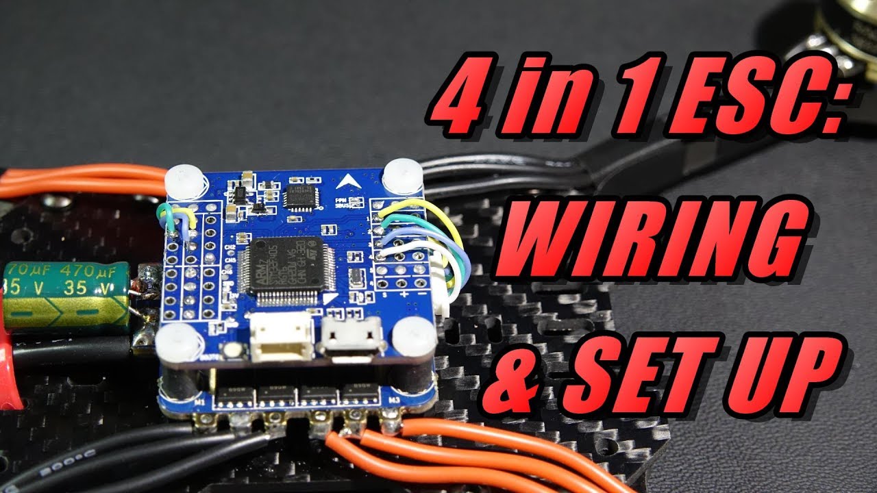
4 in 1 ESC Wiring & Set Up
Wiring anniversary special edition racestar rev35a - Help ...

Typhoon Bolt32 V2 4in1 ESC 4x35A
4in1 ESC 45A

All-in-one FC/PDB and 4-in-1 ESC wiring -- series or parallel ...

Finally! How To Wire Any 4 in 1 ESC
How to wire a 4 in 1 ESC on Matek F405-CTR Flight Controller ...

Quadcopter wiring diagram guide - Rcdronegood.com

How To Connect Quadcopter Motors and ESC
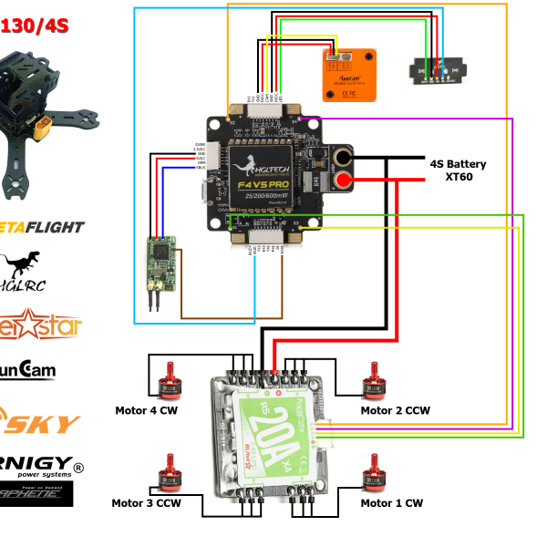
Wiretap's 130mm 4S FPV Racer

Hakrc 15 Amp 4-in-1 Brushless ESC 20x20mm Mounting 15A Blheli_S BB2 2-4S Dshot for RC FPV Racing Drone

Holybro Tekko32 F4 Metal 65A 4in1 ESC

Finally! How To Wire Any 4 in 1 ESC - YouTube

Lumenier 35A 4-in-1 ESC to CLRacing F4s JST Wiring Diagram ...

XRotor Micro 40A 4in1 BLHeli-S DShot600_Discontinued ...
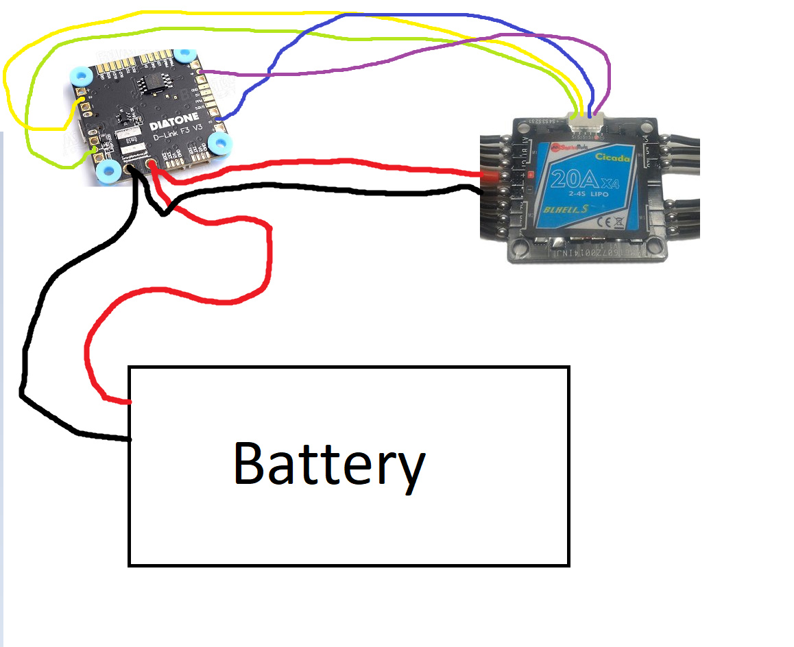
Wiring Cicada 4 in 1 ESC to Diatone FC with integrated PDB ...

How to setup BLHeli32 ESC Telemetry & Current Sensor - Oscar ...

DYS 4in1 F20A ESC Overview - Oscar Liang

Zeez RC 45A BLHeli_32 4-In-1 ESC V2 – defianceRC
![Hobbywing XRotor Micro 4in1 ESC & F4 G3 Flight Controller Combo [HWA38040302]](https://images.amain.com/images/large/hwa/hwa38040302.jpg)
Hobbywing XRotor Micro 4in1 ESC & F4 G3 Flight Controller Combo [HWA38040302]

Bardwell 32Bit 4in1 30A 6S ESC
0 Response to "41 4 in 1 esc wiring diagram"
Post a Comment