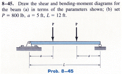
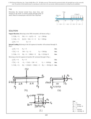
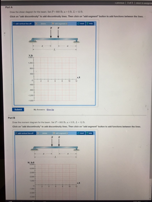
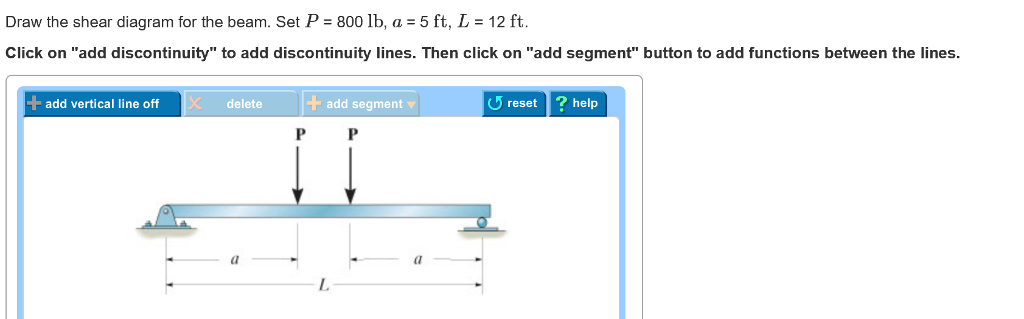
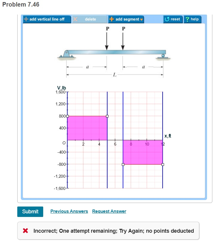
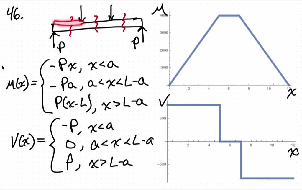
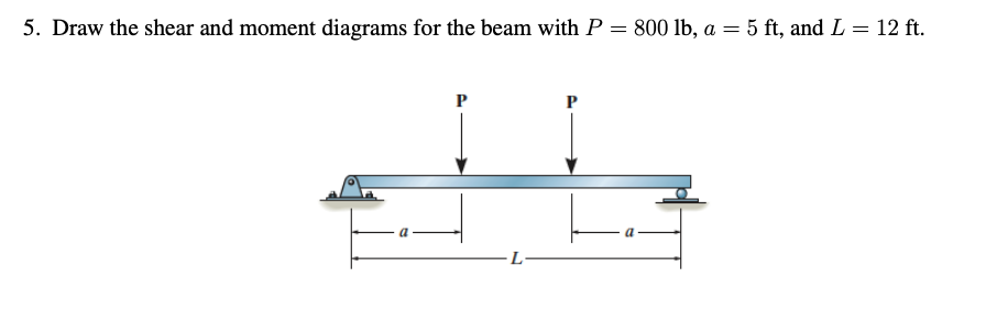
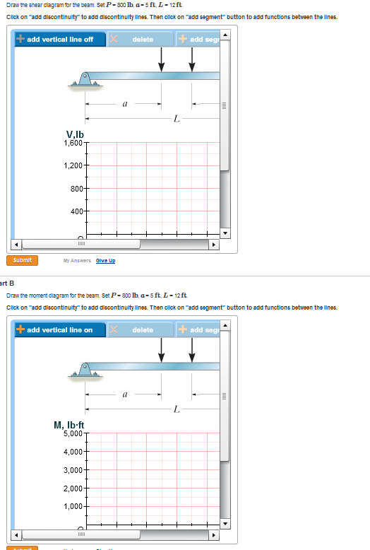
44 draw the shear diagram for the beam. set p = 800 lb, a = 5 ft, l = 12 ft.
Draw The Shear Diagram For The Beam - Free Diagram For Student The shear diagram is now at 1167 lb on the positive side. How to draw moment and shear diagrams in beams. About the beam calculator. In other words the line will be sloped. 3 determine the shear throughout the beam as a functions of x where 0 is less than or equal to x and 6ft is greater than or... Draw The Shear Diagram For The Beam - Drivenhelios Shear force and bending moment diagram practice problem 1. If you think this article of draw the shear and moment diagram for the beam is good for you please share this wonderful science diagram diagram link content for your diagram reference.
Free Online Beam Calculator | SkyCiv Engineering Free online beam calculator that calculates the reactions, deflection and draws bending moment and shear force diagrams for cantilever or simply Use this steel i beam span calculator to determine the reactions at the supports, draw the shear and moment diagram for the beam and calculate the...

Draw the shear diagram for the beam. set p = 800 lb, a = 5 ft, l = 12 ft.
25 Great Fishbone Diagram Templates & Examples [Word, Excel, PPT] This diagram makes it easier for one to display many potential causes for a specific effect or problem. He introduced this diagram for the quality management process in the Kawasaki shipyards. With investigation, we mean that you can carry out surveys, set up investigations etc. Structural Analysis by R C Hibbeler 8th edition(analysis of... | PubHTML5 60 ft The method of sections can be used for the calculations. For example, FHI 15 ft when the unit load is at joint I 1x = 20 ft2, Fig. Draw the influence line for the shear in panel CD of girder. Determine the maximum positive live If the beams also support a uniform dead load of 700 lb/ft... Draw The Shear Diagram For The Beam - Drivenheisenberg Draw the moment diagram for the beam. The shear diagram is now at 1167 lb on the positive side. 3 determine the shear throughout the beam as a functions of x where 0 is less than or equal to x and 6ft is greater than or Draw Moment And Shear Diagram For Beam Uvoc Rennsteigmesse De.
Draw the shear diagram for the beam. set p = 800 lb, a = 5 ft, l = 12 ft.. 10 Best Free Online Drawing Software - 2022 - iLovePhD Free Online Drawing Software Tools 2022: To draw, create, or make figures10 free online drawing tools research paper and thesis diagrams. There are hundreds of drawing tools available online but choosing the right diagrammatic tool to draw the figures in our thesis is quite complicated also a... 38 Draw The Shear Diagram For 0 - Free Catalogs A to Z L 12 ft. 6 hours ago To draw the Shear Diagram: 800 lb of shear force is uniformly distributed along segment AB. Draw the shear and moment diagrams for the beam, and determine the shear and moment throughout the beam 10 kip 2 kip/ft g Kip 8 kip 40 kip.ft as functions of x. Support Reactions... PDF BTU and Efficiency Venting: Section 3 Venting configuration complies with vent diagrams. Venting installed, fastened, and secured in place maintaining proper clearance. For a detailed diagram of allowed termination locations, see. Appendix A. • Once the termination location has been established refer to the. Fishbone Diagram (Meaning, Examples) | Draw Ishikawa Diagram Fishbone diagram or Ishikawa diagram is a modern quality management tool that explains the cause and effect relationship for any quality issue that has arisen or that may arise. It provides the visual representation of all the possible causes for a problem to analyze and find out the root cause.
Draw The Shear Diagram For The Beam - Drivenheisenberg Draw the moment diagram for the beam. The shear diagram is now at 1167 lb on the positive side. 3 determine the shear throughout the beam as a functions of x where 0 is less than or equal to x and 6ft is greater than or Draw Moment And Shear Diagram For Beam Uvoc Rennsteigmesse De. Structural Analysis by R C Hibbeler 8th edition(analysis of... | PubHTML5 60 ft The method of sections can be used for the calculations. For example, FHI 15 ft when the unit load is at joint I 1x = 20 ft2, Fig. Draw the influence line for the shear in panel CD of girder. Determine the maximum positive live If the beams also support a uniform dead load of 700 lb/ft... 25 Great Fishbone Diagram Templates & Examples [Word, Excel, PPT] This diagram makes it easier for one to display many potential causes for a specific effect or problem. He introduced this diagram for the quality management process in the Kawasaki shipyards. With investigation, we mean that you can carry out surveys, set up investigations etc.
Draw the Axial, Shear, and Moment Diagrams for the frames ...
329 6–1. Draw the shear and moment diagrams for the shaft ...
Solved Draw the shear and bending-moment diagrams for the ...
Chapter 7
Solved Draw the shear and moment diagrams for the beam (a ...

Shear and Moment Diagrams Example

V & M Diagrams | PDF | Bending | Beam (Structure)
Exercises Corresponding to Section 7.1 7–18 Determine the ...
Chapter 7
Hibbeler R.C. Structural Analysis
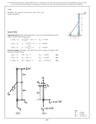
536 •7–1. Determine the internal normal force and shear force ...

PDF) Chapter 06 | Andres Hernandez - Academia.edu
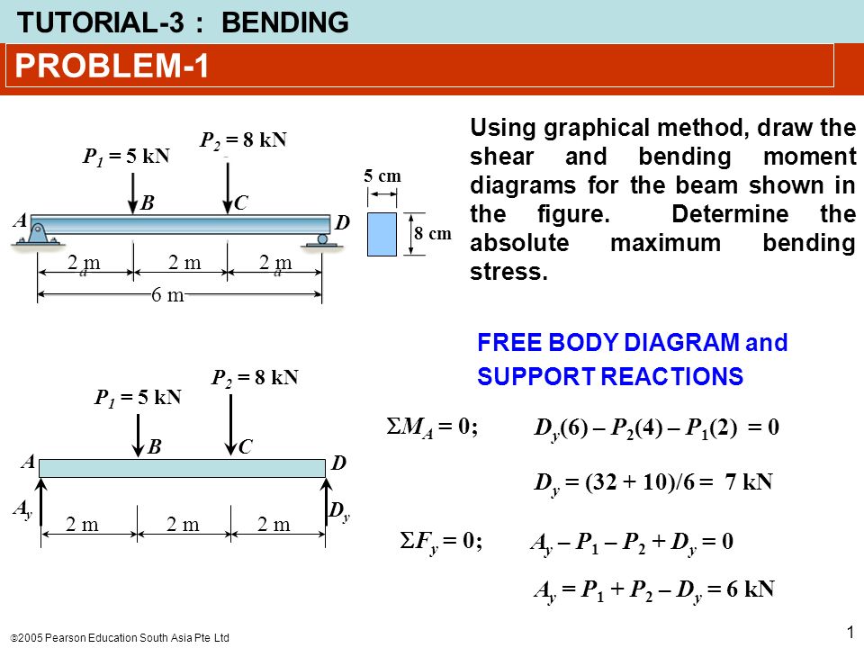
PROBLEM-1 Using graphical method, draw the shear and bending moment diagrams for the beam shown in the figure. Determine the absolute maximum bending.
Answered: Draw the shear diagram for the beam.… | bartleby
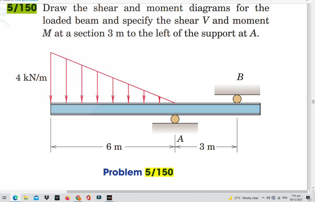
Answered: 5/150 Draw the shear and moment… | bartleby
Solved Draw the shear diagram for the beam. Set P = 800 lb ...
Solved Draw the shear diagram for the beam. Set P-800 lb ...
7 Solutions 44918
Chapter 7
Solved Draw the shear diagram for the beam. Set P = 800 lb ...
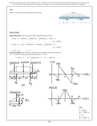
SOLUTION
Chapter 7
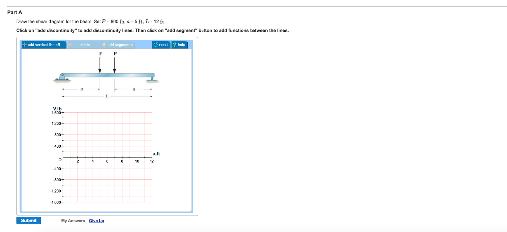
Solved Part A Draw the shear diagram for the beam. Set P 800 ...
Strength of Materials 4th edition Solution

Draw the shear and moment diagrams for the beam in terms of ...
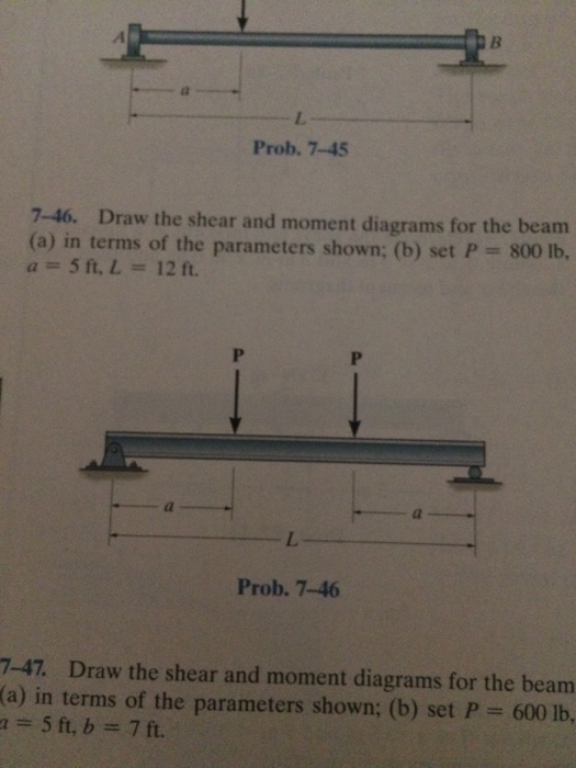
Solved Draw the shear and moment diagrams for the beam (a ...
Hibbeler R.C. Structural Analysis
Hibbeler R.C. Structural Analysis
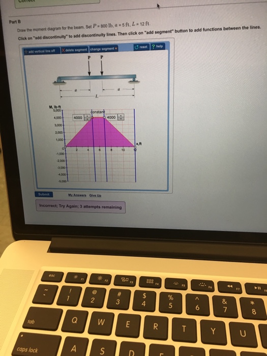
Solved Draw the moment diagram for the beam. Set P = 800 lb ...
draw the shear and moment diagrams for the beam a in terms of the parameters shown b set p800 mathrm
SOLUTION

L_2021269EN.01006501.xml
Solved 5. Draw the shear and moment diagrams for the beam ...

Draw the shear and moment diagram for the beam (a)in terms of ...

HW 5 SOLNS - CE 240 HW#5 SOLUTIONS 1 FALL 2016 Draw the shear ...

Drawing Shear and Moment Diagrams for Beam
SOLUTION
Draw the shear diagram for the beam Set P - 800 lb a | Chegg.com
Hibbeler R.C. Structural Analysis
SOLUTION

Statics 7.45 - Draw the shear and moment diagrams for the shaft in terms of the parameters shown.
Shear Forces and Bending Moments
Exercises Corresponding to Section 7.1 7–18 Determine the ...
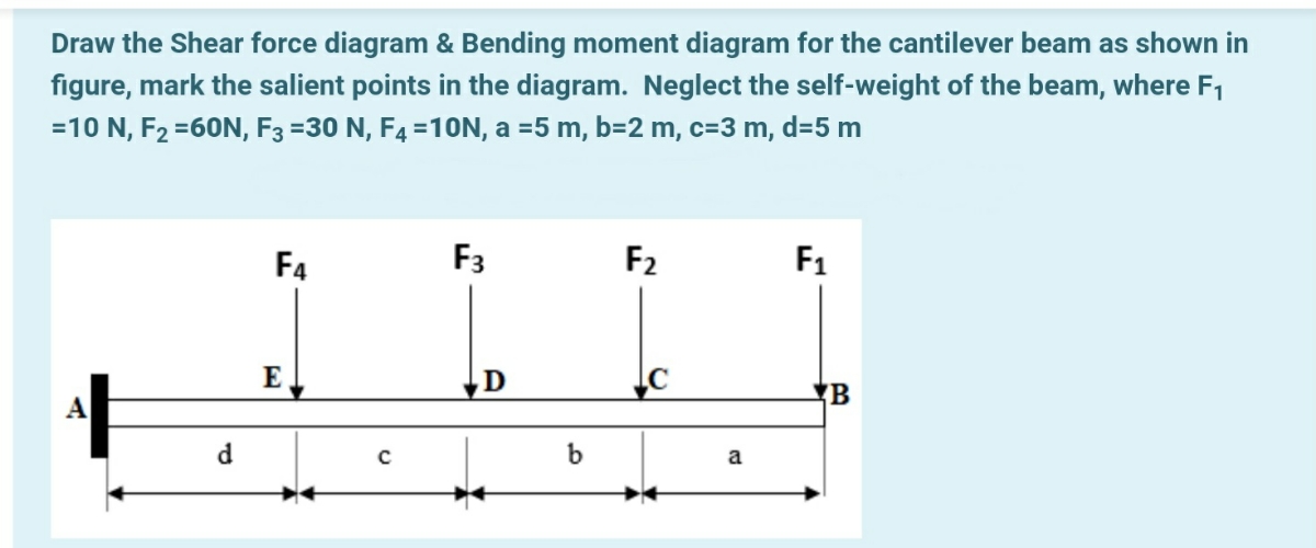
Answered: Draw the Shear force diagram & Bending… | bartleby
0 Response to "44 draw the shear diagram for the beam. set p = 800 lb, a = 5 ft, l = 12 ft."
Post a Comment