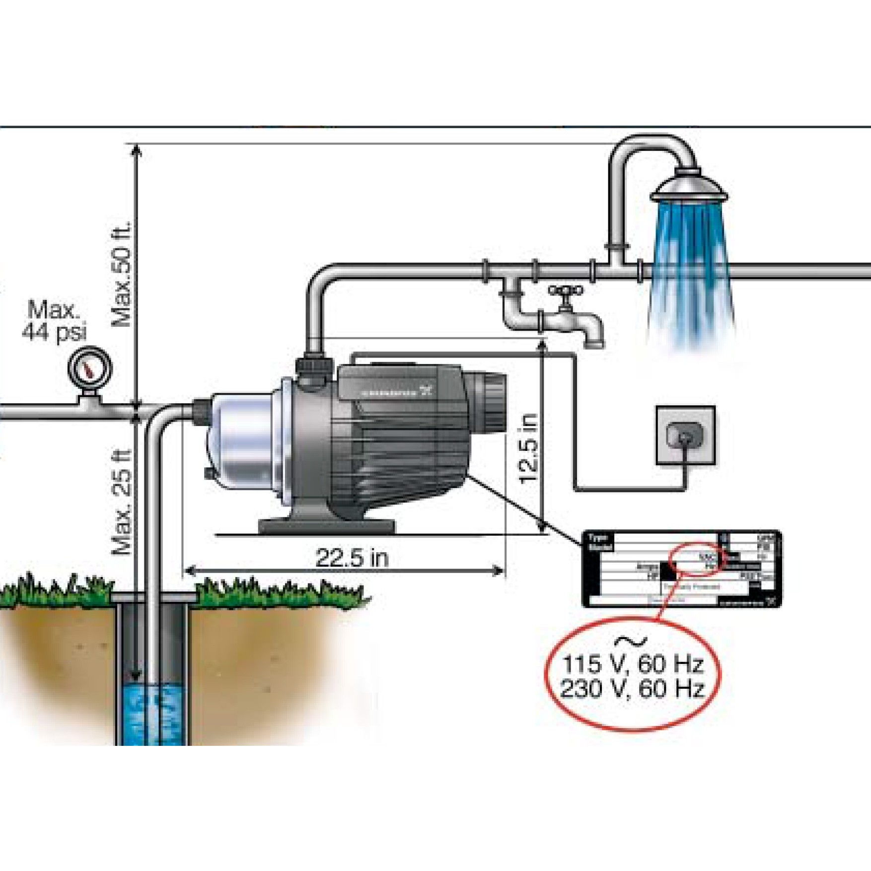
42 booster pump installation diagram
Polaris Pump Pb4-60 Wiring Diagram The Polaris booster pump supplies high pressure water to The booster pump motor is factory wired for cleaner, refer to the Typical Installation diagram. I have a new polaris pb booster pump that I bought to replace an PB Q, both V old pump had wire diagram for connections. Wiring: Grundfos Booster Pump - Tommy Car Wash Systems Attached is the TYPICAL Grundfos Booster pump wiring diagram please check confirm with your own wiring diagrams and electrician . this is the same pump for the main line booster
Pool Plumbing Diagram & Layout Schematic Examples Be sure to carefully analyze your swimming pool pump and filter installation diagram before creating any permanent seals. Water. Water is the central element that keeps everything in your swimming pool - systems and equipment - in excellent working order. Keep water level well-topped up to protect the spa combination plumbing equipment.
Booster pump installation diagram
PDF 12 Volt Vacuum Pump Installation Instructions 12 Volt Vacuum Pump Installation Instructions Instructions: 1. Mount the vacuum pump. 2. Connect the vacuum fittings, hoses, switch, and filter as shown in the diagram. 3. Connect the black wire from the vacuum pump to a ground. 4. Connect the red wire from the vacuum pump to one of the terminals on the vacuum switch. 5. Booster Pump - Installation Instructions - Pure Water ... Observe the directional arrows on the quick-connect fitting ports at the front of the pump, cut the inlet tube squarely and insert the ends into the appropriate ports. Cut the 1/4" tube that connects the tank to the unit squarely and insert the pressure switch so that the tank water will pass through the switch. Flow direction does not matter. PDF PB4SQ PB4SQ™ Booster Pump - Polaris® Pool H0609200_REVA PB4SQ™PB4SQ™ Booster Pump Replacement Kit Instructions Replacement Parts List ITEM Part Description SECTION PAGE 1 R0722900 Capacitor Housing Cover 4 5,8,10 2 R0734500 Capacitor 30mfd 400VAC 4 5 3 R0734200 Motor Assembly, 725 WATT 6 10 4 R0722600 Fan Cover Kit 5 6,7 5 R0723000 Motor Fan 5 6 6 R0722700 Base 5 7 7 R0747800 Mechanical Seal Assembly 6 10
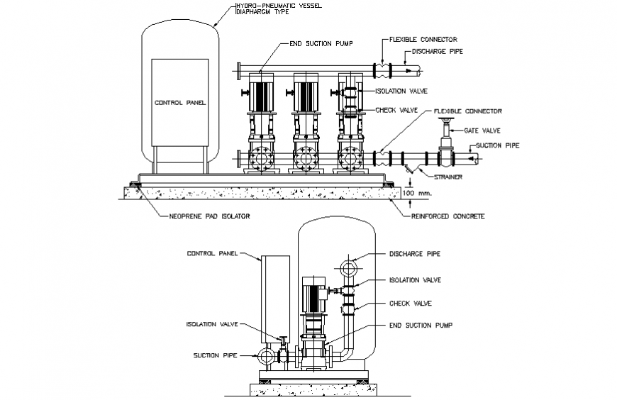
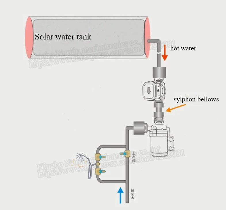
Booster pump installation diagram. PDF BOOSTER PUMP SYSTEM - AmeriWater 1. Install the booster pump system on firm level floor. 2. Inlet water supply piping should be equal or greater than the inlet pipe on the booster pump system. 3. Outlet piping from the booster pump system should be equal or greater than the outlet pipe on the booster pump system. 4. PDF Polaris Booster Pump Installation Instructions heater discharge (see the Typical Installation diagram). DO NOT TAP THE BOOSTER PUMP INLET INTO THE THREE-FOOT SECTION OF HEAT SINK PIPE THAT COMES DIRECTLY OUT OF THE HEATER. Installation with a Solar System The booster pump must be installed so it is always in the water flow (see the diagram below). Some solar heating systems are designed to use Diagram for REVERSE-OSMOSIS-BOOSTER-PUMP - H2O Distributors 1-800-955-8561. Mon - Fri • 9:00 AM - 5:30 PM ET. sales@h2odistributors.com. How to Install Booster Pump | Booster Pump Installation ... How to install a Pressure Booster PumpKnow how to pump up the water pressure in your home with the help of a pressure booster pump. Pumpkart. Com is not only...
PDF Booster Pump Installation Instructions Booster Pump Installation Instructions 1. Install pressure switch in tank line. (See diagram on back for where to place the pressure switch). 2. Pump must be located within 2 feet of pressure switch and within 6 feet of power outlet. A. Pump can be mounted to the wall horizontally in either direction or vertically only one way ~ with pump head and PDF Design Envelope 6800G and 6900 General arrangement schematic diagram 6 Design Envelope booster package commission check sheet 7 1.0 Introduction 11 2.0 Operation displays 12 3.0 Alarm management displays 17 4.0 System setup displays 18 Setup displays - level 1 and level 2 19 Wiring diagram 29 PDF Etter Engineering Engb Gas Booster Installation Instructions the booster. 4. Lower specific gravity than specified on nameplate. 5. High inlet gas temperature. If gas booster is not delivering rated pressure and motor IS overloaded, check the following: 1. Wrong voltage connections. 2. Unit attempting to pump more than rated volume. 3. Higher specific gravity than specified on nameplate. 4. Booster pump /control diagram - YouTube Check my resent upload video.. booster pump repair,booster pump and pressure tank,booster pump installation,booster pump for wash...
PDF Booster Pump Owner's Manual Model: 6060 The Hayward 6060 booster pump is specifically engineered for the demanding requirements of today's in-ground swimming pool cleaning systems. The 6060 booster pump includes an improved seal and impeller design that will provide many years of efficient, dependable, corrosion-free service. PDF Vacuum Pump Assist Installation Instructions 3. Cut the 3/8" factory brake booster hose again and insert the supplied Y-connector (Fig. #2) between the check valve and the brake booster. 4. Connect 1/8" hose from vacuum pump. (Fig. #3) 5. Next connect the red wire from pump to 12 volt source. For more information about wiring look at other side of this paper. 6. PDF SSBC Electric Brake Vacuum Pump Installation Instructions 13) Congratulations, you have completed installation of the vacuum pump! Before you start the vehicle, review the simplified wiring diagram pictures below to make sure all of your connections are correct: To ground (-) Relay terminal 3 To vacuum switch Relay terminal 1 To (-) pump (black) Relay terminal 5 (+) 12 volt Relay terminal 2 To ... PDF Installation and User'S Guide BOOST-RITE™ Universal Booster Pump Installation and User's Guide iv For Installation of Electrical Controls at Equipment Pad (ON/OFF Switches, Timers and Automation Load Center) Install all electrical controls at equipment pad, such as on/off switches, timers, and control systems, etc. to allow the operation (startup, shut-down, or servicing)
Booster Pump Questions & Answers - Residential and Light ...
PDF Stainless Steel Brakes 28146 Vacuum Pump Installation ... 13) Congratulations, you have completed installation of the vacuum pump! Before you start the vehicle, review the simplified wiring diagram pictures below to make sure all of your connections are correct: To ground (-) Relay terminal 3 To vacuum switch Relay terminal 1 To (-) pump (black) Relay terminal 5 (+) 12 volt Relay terminal 2 To ...

Shower booster pumps
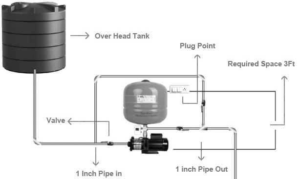
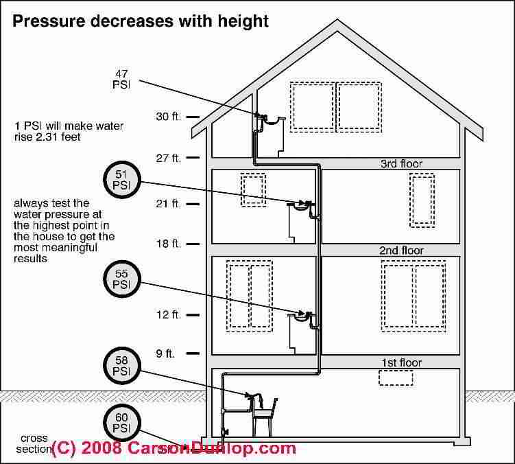
Water pressure booster pump and tank guide - water ... Installing a Booster Pump for Water Pressure on the Fourth Floor of a Residential Building Beginning on the 4th floor of such a building, install an additional pressure tank next to the second pump. The ground floor pump will send water into the incoming pipe connection of your 4th floor pump itself.

Install Pump in a Loft | How To Pages
Pb4 60 Wiring Diagram Pb4 60 Parts Diagram. The Power Behind Polaris The PB4SQ is an energy-efficient. I have a new polaris pb booster pump that I bought to replace an PB Q, both V old pump had wire diagram for connections. Electrical. The booster pump motor is factory wired for cleaner, refer to the Typical Installation diagram .
Buying a Home Booster Pump: The Complete Guide - Anchor Pumps
Diagrams --Typical Pump Installations - Water Pump Supply Diagrams --Typical Pump Installations. The information provided here is for educational purposes only. Technically qualified personnel should install pumps and motors. We recommend that a licensed contractor install all new systems and replace existing pumps and motors. Failure to install in compliance with local and national codes and ...
How Demand Pumps Work
PDF Installation Diagram - H2O Distributors Reverse Osmosis Installation Diagram 3 5 4 8 9 16 18 17 10 11 15 19 14 13 20 21 6 2 1 7 12 System Components 1.) Cold Water Line 2.) Angle Stop Shut-off Valve 3 ...
How to Install Water Pressure Booster Pumps | PumpStoreUSA.com
PDF Universal Booster Pump Installation the LA01N booster pump it manufactures, including all parts and components thereof, to be free of defects in material and workmanship. The warranty commences on the date of installation of the pump and shall remain in effect for a period of twelve months, but in no

Installation scheme of a centrifugal pump station (Booster No ...
PDF Owner'S Manual • Pump is exceptionally quiet, and uses up to 40% less electricity than competitive booster pumps. • Pump design allows for easy installation and service. • Suitable for use with all pressure cleaners requiring a booster pump. • Tall mounting base allows for increased motor ventilation as well as protection from flooding.

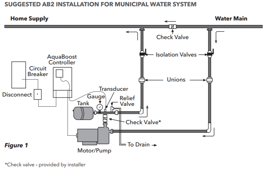
FIG 1 Pressure Booster Pump Application - Manuals+
Water Pump Setup Diagram - U Wiring Submersible Pump Control Box Wiring Diagram For 3 Wire Single Phase Submersible Pump Submersible Electrical Circuit Diagram. Automatic Water Level Controller Wiring Diagram For 3 Phase Motor Submersible Pump Water Pump Motor Submersible Pump Electrical Installation. Booster Pump Explain New 2017 Youtube Well Pump Refrigeration And Air ...
Packaged Pressure Booster Systems
How to Install Water Pressure Booster Pumps - PumpStoreUSA.com For most people, installation will be in-line with a municipal water supply, as illustrated below: For other applications, the pump may be installed with a flooded suction line to a tank, as shown here: Other users may install these pressure-booster pumps in a well-service application, as shown below: Prices subject to change without notice.

Install Single Shower Pump
PDF Polaris Booster Pump Installation Instructions The starting current of the booster pump motor may exceed 15 amps. It is recommended that a 20 amp service breaker be used for the pump. The booster pump motor is factory wired for 240 volts, but can be wired for either 120 or 240 volts. To rewire to 120 volt, follow the instructions on the name plate
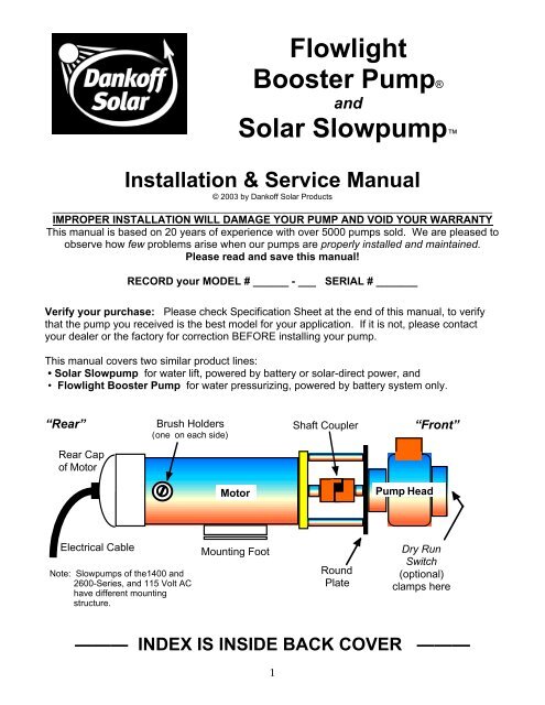
Conergy Slowpump Manual - Energy Matters
PDF INLINE PRESSURE BOOSTING SYSTEM - Lowe's Internal Wiring Diagram Inline 400 Inline 400 Model No. 92061501 / 92061503 92061502 / 92061504 ... The Inline 400 is a simple to use "plug-and-play" water pressure booster system. At the heart of this fully integrated booster system is a trusted ... Decide on a location for the pump installation that is suitable based on the enclosure ...
How RO Booster Pumps Work
PDF PB4SQ PB4SQ™ Booster Pump - Polaris® Pool H0609200_REVA PB4SQ™PB4SQ™ Booster Pump Replacement Kit Instructions Replacement Parts List ITEM Part Description SECTION PAGE 1 R0722900 Capacitor Housing Cover 4 5,8,10 2 R0734500 Capacitor 30mfd 400VAC 4 5 3 R0734200 Motor Assembly, 725 WATT 6 10 4 R0722600 Fan Cover Kit 5 6,7 5 R0723000 Motor Fan 5 6 6 R0722700 Base 5 7 7 R0747800 Mechanical Seal Assembly 6 10
GOULDS BOOSTER PUMPS BUYERS GUIDE
Booster Pump - Installation Instructions - Pure Water ... Observe the directional arrows on the quick-connect fitting ports at the front of the pump, cut the inlet tube squarely and insert the ends into the appropriate ports. Cut the 1/4" tube that connects the tank to the unit squarely and insert the pressure switch so that the tank water will pass through the switch. Flow direction does not matter.

Booster Pump - an overview | ScienceDirect Topics
PDF 12 Volt Vacuum Pump Installation Instructions 12 Volt Vacuum Pump Installation Instructions Instructions: 1. Mount the vacuum pump. 2. Connect the vacuum fittings, hoses, switch, and filter as shown in the diagram. 3. Connect the black wire from the vacuum pump to a ground. 4. Connect the red wire from the vacuum pump to one of the terminals on the vacuum switch. 5.

Hayward Booster Pump

Reverse Osmosis System w/ Booster Pump Installation Guide
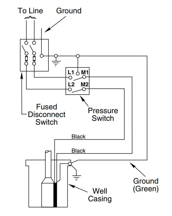
How to Install and Wire a Well Pump - Well Pump Installation ...
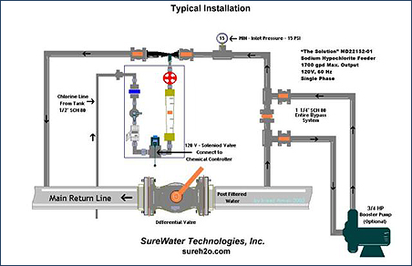
SureWater Technologies Inc.
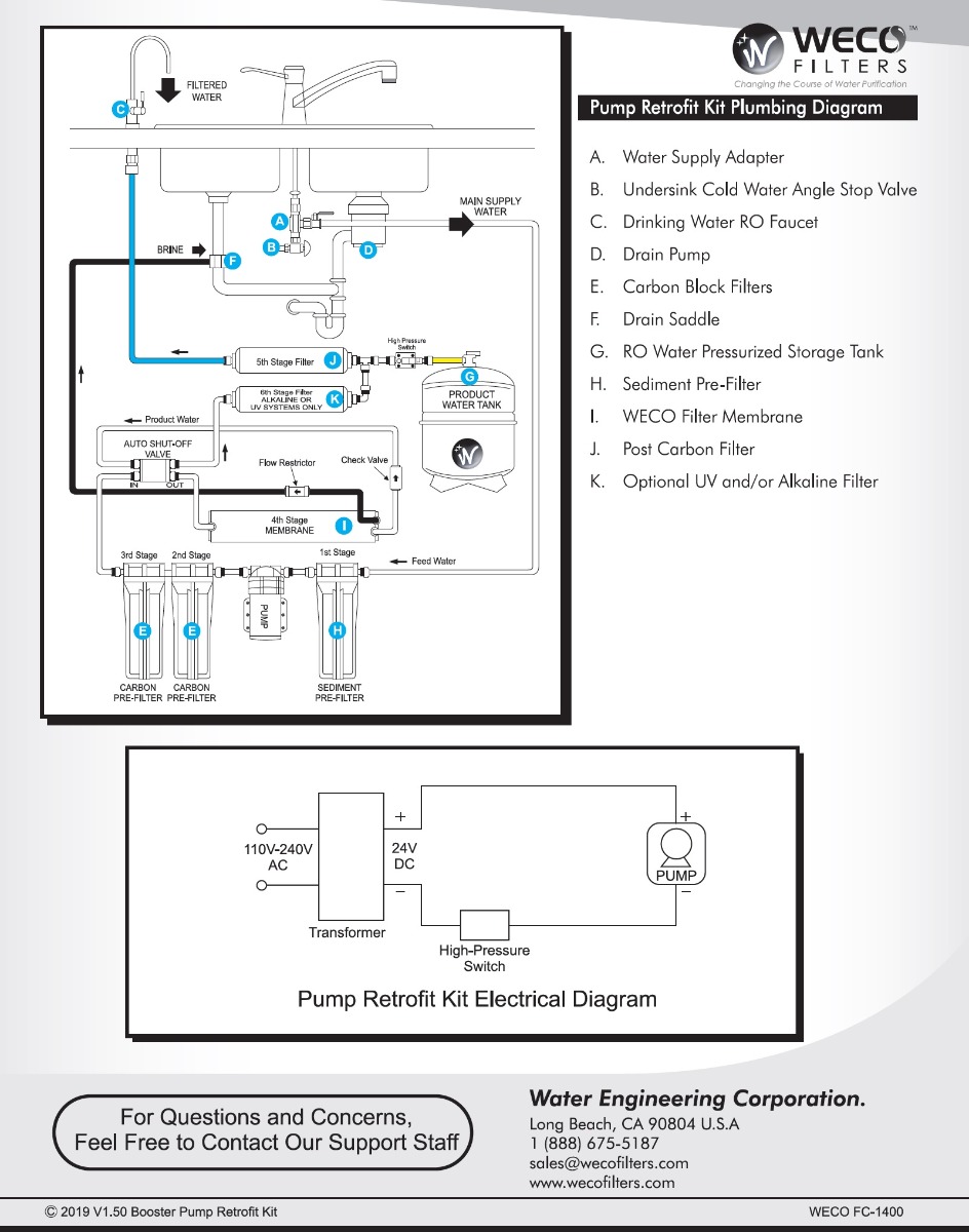
Installing FC-1400 RO Booster Pump Retrofit Kit - Video

Pressure pump installation user guide with full details
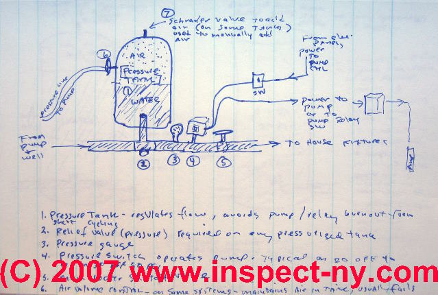
Photo Guide to Well Water Pump Controls & Switches - private ...
Vanora Pumps | Pressure Booster pumps | Inline pumps ...
5 Stage Point of Use RO System with Feed Booster Pump

Hayward Booster Pump

Hayward Booster Pump
A.Y. McDonald 6010-007 DuraMAC™ 3/4 hp Booster Pump ...
/Residentialwaterpump-GettyImages-155144312-592d8e713df78cbe7e13aaac.jpg)
Pressure Booster Pump for Plumbing

Flint and Walling Typical Piping Diagrams | Water well hand ...

Water Pressure Booster Pump Installation (10 Step Guide ...
Booster Pump Package Operating & Installation Instructions

Jet Pumps / Centrifugal Pumps Installation shallow well or ...
Grundfos MQ3-45 - 1 HP Pressure Booster Pump
Booster Pump
Water pressure booster pump and tank guide - water pressure ...
How to Install Water Pressure Booster Pumps | PumpStoreUSA.com
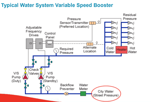
Domestic Water “Pressure Booster Pumping System” – Suction ...

Grundfos CMBE5-62 Inverter Low Noise Home Water Pump Water ...
Booster water pump electric installation and plumbing details ...

Backup Water Systems | RPS Solar Pumps | America's #1 Solar ...

Cleanwater Overview - Red Lion

Booster pump /control diagram
60w Dc 24v 15m Shower Booster Pump Brushless Motor Impeller ...
0 Response to "42 booster pump installation diagram"
Post a Comment