41 draw a ray diagram representing your experiment from part c
Concave Mirrors And Convex Mirrors - Image Formation, Ray ... Ray diagrams help us trace the path of the light for the person to view a point on the image of an object. Ray diagram uses lines with arrows to represent the incident ray and the reflected ray. It also helps us trace the direction in which the light travels. Plane Mirror vs Spherical Mirrors PDF Q1.€€€€€€€€€ (a)€€€€ The diagrams below show the patterns ... The diagram shows two rays of light coming from a small fish in some water. The rays enter a person's eye. (c)€€€€ The person sees an image of the fish under the water. On the diagram, draw construction lines to find the position of the image. Label the image I. 1 mark (d)€€€€ In some parts of the world, people catch fish using ...
chapter 24, 25, 26 Flashcards - Quizlet The ray shown is one of the principal rays for the lens. Each square is 1.5 cmcm along the horizontal direction, but the vertical direction is not to the same scale. Use information from the diagram to answer the following questions: Using only the ray shown, decide what type of lens this is. converging. Part B (Figure 1) shows a small plant near a thin lens. The ray shown is …

Draw a ray diagram representing your experiment from part c
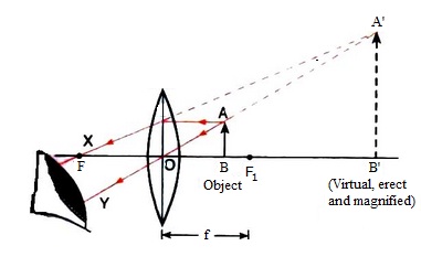
Atomic Spectra and X-rays – University Physics Volume 3 A standard X-ray image provides a two-dimensional view of the object. However, in medical applications, this view does not often provide enough information to draw firm conclusions. For example, in a two-dimensional X-ray image of the body, bones can easily hide soft tissues or organs. The CAT (computed axial tomography) scanner addresses this ... (a) Draw ray diagram of refraction of light through a ... Click here👆to get an answer to your question ️ (a) Draw ray diagram of refraction of light through a prism and explain the phenomenon of dispersion of light.(b) Write the formula for lens power and define its unit. Ray diagrams and images - Lenses - Edexcel - GCSE Physics ... A virtual image appears to come from behind the lens. To draw a ray diagram: Draw a ray from the object to the lens that is parallel to the principal axis. Once through the lens, the ray should...
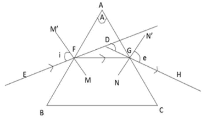
Draw a ray diagram representing your experiment from part c. PDF GEOMETRICAL OPTICS - Boston University 5. Redraw Figure 9 for your lab report to practice ray tracing . 6. Is the image upright or inverted? Is the magnification greater or less than one? Describe the image. Also include the following in your lab report as part of Experiment 1: 7. Make a ray diagram for an object placed closer to a diverging (concave) lens than the focal point. (a) Draw a ray diagram to show refraction of a ray of ... a) The phenomenon of refraction for a ray of monochromatic light passing through a glass prism is shown as below: Let, PQR be the principal section of the prism. The refracting angle of prism is A. Monochromatic light EF is incident on face PQ at angle of incidence i1. This ray enters from a rarer to denser medium and hence is refracted towards the normal FN. Solved object 3. The diverging mirror shown above has a ... This ray heads toward F, emerging parallel to the principal axis after reflection. Ray 2 is analogous to ray 1, except that the reflected, rather than the incident, ray is parallel to the principal axis. Ray 3. This ray travels toward the center of curvature C; as a result, the ray strikes the mirror perpendicularly and reflects back on itself. PDF - PapaCambridge 7 (a) In the space below, draw a diagram to represent a sound wave. On your diagram, mark and label (i) two consecutive compressions and two consecutive rarefactions, (ii) the wavelength of the wave. [3] (b) Fig. 7.1 shows part of the electromagnetic spectrum. X-RAYS INFRA- RED Fig. 7.1
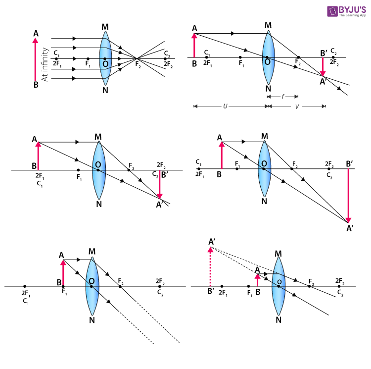
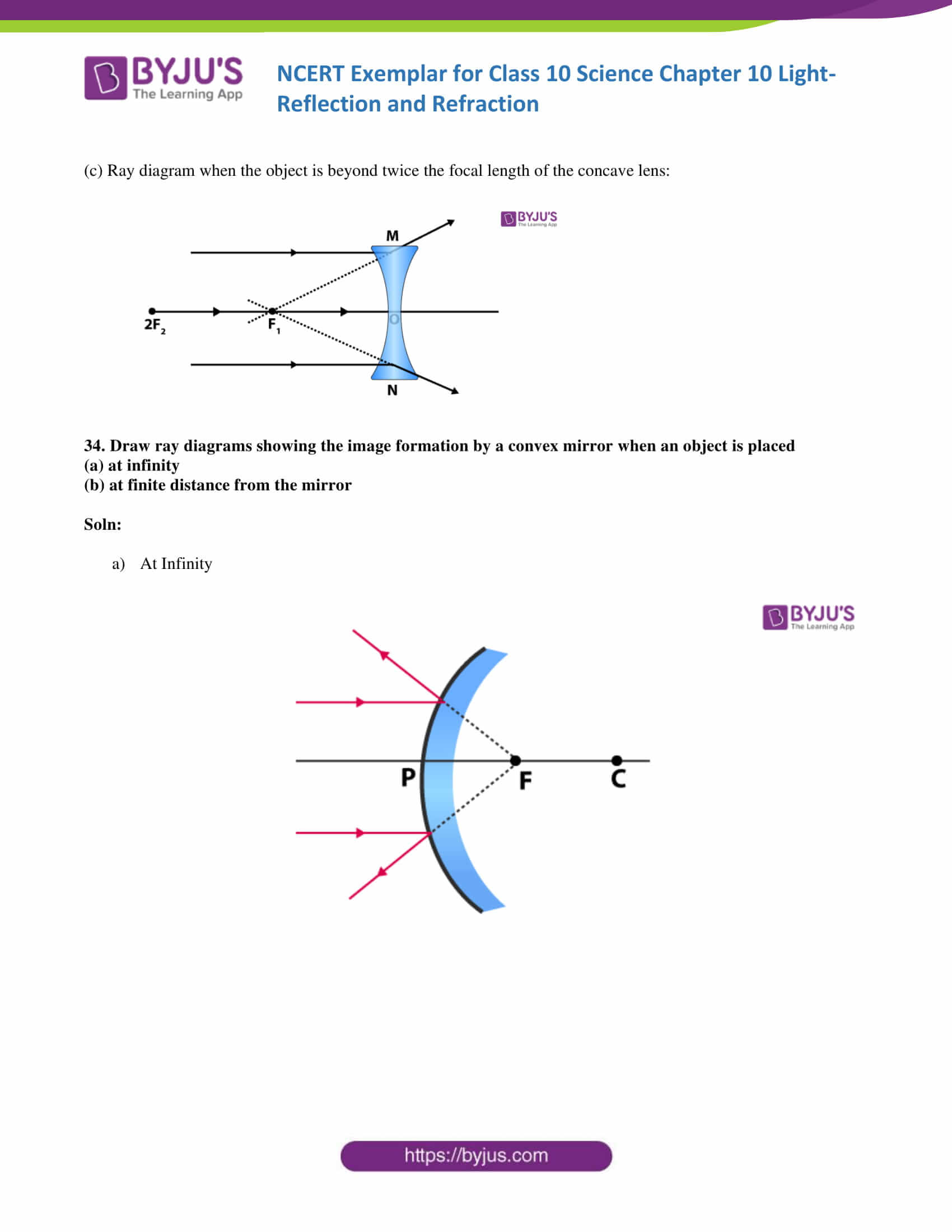
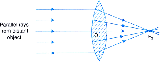
Important Question for Class 10 Science Light Reflection ... 8. Redraw the given diagram and show the path of the refracted ray: [All India(C)] Answer. 9. Draw the following diagram in your answer book and show the formation of image of the object AB with the help of suitable rays. [All India] Answer. 10. Which kind of mirrors are used in the headlights of a motor-car and why? [Foreign] Answer. Convex & Concave Lens Ray Diagrams | How to Draw Ray ... The steps in drawing a convex lens ray diagram are as follows: Step 1 Draw the first incident ray (Ray 1) from the tip of the object parallel to the principal axis. Lakhmir Singh Physics Class 10 Solutions Chapter 5 ... Draw ray diagrams to represent the nature, position and relative size of the image formed by a convex lens for the object placed : ... (c) Draw a ray diagram to show the formation of image. Mark clearly F and 2F in the diagram. ... A student did an experiment with a convex lens. He put an object at different distances 25 cm, 30 cm, 40 cm, 60 cm ... Image formation by convex and concave lens ray diagrams Image formation by convex lens ray diagrams. Image formation in a convex lens can be explained with the help of three principal rays shown in the figure. The ray parallel to the principal axis passes through the focal point after refraction by the lens. The ray passing through optical centre passes straight through the lens and remains undeviated.
Ray Diagrams for Lenses - Georgia State University Ray Diagrams for Lenses. The image formed by a single lens can be located and sized with three principal rays. Examples are given for converging and diverging lenses and for the cases where the object is inside and outside the principal focal length. The "three principal rays" which are used for visualizing the image location and size are: physical chemistry: kinetics Flashcards | Quizlet Draw a diagram of a suitable apparatus needed to perform the experiment outlined in part (a). Include in your diagram a method for collecting and measuring the carbon dioxide. The apparatus should be airtight. PDF LABORATORY I: GEOMETRIC OPTICS - University of Minnesota On your original diagram, add the light rays that would make it from the light source in its new position to the screen. How would the position of the light spot on the screen change? 3. Draw a new ray diagram for a similar situation with a new light source, in the shape of a vertical arrow that emits light from all parts. Physics Tutorial: Ray Diagrams - Convex Mirrors A ray diagram shows the path of light from an object to mirror to an eye. A ray diagram for a convex mirror shows that the image will be located at a position behind the convex mirror. Furthermore, the image will be upright, reduced in size (smaller than the object), and virtual. This is the type of information that we wish to obtain from a ray diagram.
q39-draw-a-ray-diagram-to-show | LIDO
(b) Find the distance of the image from the ... - Toppr Ask Click here👆to get an answer to your question ️ A spherical mirror produces an image of magnification - 1 on a screen placed at a distance of 50 cm from the mirror.(a) Write the type of mirror.(b) Find the distance of the image from the object.(c) What is the focal length of the mirror ?(d) Draw the ray diagram to show the image formation in this case.
A Set of Virtual Experiments of Fluids, Waves, Thermodynamics ...
Light Reflection and Refraction Class 10 ... - Learn Cram Draw the following diagram in your answer book and show the formation of image of the object AB with the help of suitable rays. (CBSE 2008) Answer: Question 2. Draw ray diagrams to represent the nature, position and relative size of the image formed by a convex lens for the object placed: (a) At 2F

Recent advances in ultraviolet nanophotonics: from plasmonics ...
(PDF) Architectural Graphics - 6th Edition (2015 ... Architectural Graphics - 6th Edition (2015) 275 Pages. Architectural Graphics - 6th Edition (2015)

Ray Diagrams & Lenses: Physics Lab Video
Geometrical Optics: Focal Length of a Concave Mirror and a ... The u-v method to find focal length of a given concave mirror or convex lens consists of following steps . For an appropriate object distance u, find the image distance v.Measure u and v.; Repeat above step at few more object distances. Get the focal length from all measurements by (a) taking average of calculated f or (b) from u versus v graph or (c) from versus graph.

Draw a ray diagram in each of the following cases to show the ...
Ray Diagrams - Physics Classroom The description is applied to the task of drawing a ray diagram for an object located beyond the 2F point of a double convex lens. 1. Pick a point on the top of the object and draw three incident rays traveling towards the lens. Using a straight edge, accurately draw one ray so that it passes exactly through the focal point on the way to the lens.
Color mismatch and observer metamerism between conventional ...
Physics Tutorial: Ray Diagrams for Plane Mirrors This section of Lesson 2 details and illustrates the procedure for drawing ray diagrams. Let's begin with the task of drawing a ray diagram to show how Suzie will be able to see the image of the green object arrowin the diagram below. For simplicity sake, we will suppose that Suzie is viewing the image with her left eye closed. Thus, we will focus on how light travels from the two extremities of the object arrow (the left and right side) to the mirror and finally to Suzie's right eye as she sights at the image. The four steps of the process for drawing a ray diagram are listed, described and illustrated below. 1. Draw the image of the object. 2. Pick one extreme on the image of the object and draw the reflected ray that will travel to the eye as it sights at this point. 3. Draw the incident ray for light traveling from the corresponding extreme on the object to the mirror. 4. Repeat steps 2 and 3 for all other extremities on the object.
To Find Image Distance For Varying Distance Of A Concave Lens
Selina Solutions Concise Physics Class 10 Chapter ... - BYJUS In each case, draw a diagram to show the path taken by the ray as it passes through the glass slab and emerges from it. Solution: (i) When the angle of incidence is 0 0 (ii) When the angle of incidence is 45 0. Question: 26. In the adjacent diagram, AO is a ray of light incident on a rectangular glass slab.
Lakhmir Singh and Manjit Kaur Solutions for Class 10 Physics ...
Concise Physics Part II - Selina Solutions for Class 10 ... A ray of green light enters a liquid from air, as shown in the figure. The angle 1 is 45 o and angle 2 is 30 o. (a) Find the refractive index of liquid. (b) Show in the diagram the path of the ray after it strikes the mirror and re-enters in air.
NCERT Exemplar Class 10 Science Solutions Chapter 10
PDF Chapter 22: Mirrors and Lenses - SharpSchool your head. Use the sketch in Fig. 22.3a to help draw a ray diagram. The vertical distance between the feet and eyes is h 1; the vertical distance between the top of the head and the eyes is h 2; and h 1 h 2 h (Fig. 22.3b). You will see a toe if a ray from your toe reaches your eye after reflection. This is ray 1 on the diagram.

Draw a ray diagram to show how a converging lens can form an ...
Ray diagrams - Reflection and refraction of light - CCEA ... On a sheet of white paper draw a pencil line - label this AB. Using a protractor, draw a normal at C, roughly the middle of AB. Draw a line at 20o to the normal. Position a plane mirror carefully...

PDF) Brillouin Scattering and its Application in Geosciences
Physics Tutorial: Refraction and the Ray Model of Light These three rules will be used to construct ray diagrams. A ray diagram is a tool used to determine the location, size, orientation, and type of image formed by a lens. Ray diagrams for double convex lenses were drawn in a previous part of Lesson 5. In this lesson, we will see a similar method for constructing ray diagrams for double concave ...

The Law of Refraction | Physics
Solved Part A Consider the following diagrams noting that ... Transcribed image text: Part A Consider the following diagrams noting that the scale is different between diagrams. In these diagrams, C and F represent the center of curvature and the focal point of the convex mirror, respectively. The image formed by the mirror is obtained using the ray tracing technique.

Draw a ray diagram to show the object is placed in front of ...
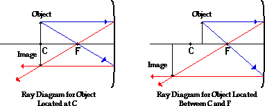
Physics Tutorial: Ray Diagrams - Concave Mirrors The method for drawing ray diagrams for concave mirror is described below. The method is applied to the task of drawing a ray diagram for an object located beyond the center of curvature (C) of a concave mirror. Yet the same method works for drawing a ray diagram for any object location. 1. Pick a point on the top of the object and draw two ...

Draw a ray diagram to show the path of light when it travels ...
Celebrities Archives | Hollywood.com Click to get the latest Celebrities content. Sign up for your weekly dose of feel-good entertainment and movie content!

To Find Image Distance For Varying Distance Of A Concave Lens
Ray Diagrams - Isaac Physics The first ray to draw will go from the top of the object towards the centre of curvature of the mirror, although it will not get there (the dashed line is a construction line added to make the diagram clearer, it does not represent the path of a ray). This ray is reflected back along the same path.
Draw A Ray Diagram Representing Your Experiment From Part C ...
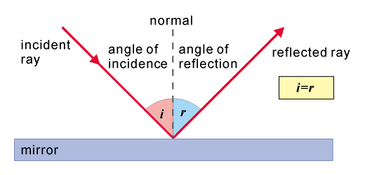
PDF Part 1 Angle of Incidence, Angle of Reflection 3. From this experiment, determine the positions where you can see the pin with your open eye. Draw light rays on the diagram below to support your hypothesis. Remember, the light rays come from the object and go to the eye. 4. Philosophy alert: If you observe the image of the object, and then close your eyes, does the image still exist? Explain.
Textiles | Free Full-Text | A Review of the Mechanical and ...
Ray diagrams and images - Lenses - Edexcel - GCSE Physics ... A virtual image appears to come from behind the lens. To draw a ray diagram: Draw a ray from the object to the lens that is parallel to the principal axis. Once through the lens, the ray should...
3.16 draw ray diagrams to illustrate reflection and ...
(a) Draw ray diagram of refraction of light through a ... Click here👆to get an answer to your question ️ (a) Draw ray diagram of refraction of light through a prism and explain the phenomenon of dispersion of light.(b) Write the formula for lens power and define its unit.
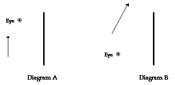
Physics Tutorial: Ray Diagrams for Plane Mirrors
Atomic Spectra and X-rays – University Physics Volume 3 A standard X-ray image provides a two-dimensional view of the object. However, in medical applications, this view does not often provide enough information to draw firm conclusions. For example, in a two-dimensional X-ray image of the body, bones can easily hide soft tissues or organs. The CAT (computed axial tomography) scanner addresses this ...

Cathode-ray tube - Wikipedia
By drawing ray diagrams, explain the formation of image when ...

Four students A, B, C and D performed an experiment to determine the focal length of a convex lens by using a lighted candle kept at a considerable distance as the object. They represented the ...
Ray Diagram PRELAB LAB

Ray diagram for image formation of an extended object ...
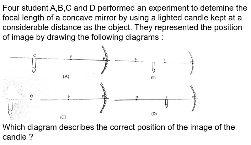
Four students A, B, C and D performed an experiment to ...

Solved 1. Which of the following ray diagrams is correct ...
Solved 1. Converging Lenses The pre-lab notes described how ...

Drawing Ray Diagrams for a Plane Mirror
Physics Tutorial: Ray Diagrams - Concave Mirrors

Introduction of a Stress State Criterion to Predict Bond ...

a) Draw ray diagram of refraction of light through a prism ...
Draw a ray of diagram to show the angle of deviation class 10 ...

12.5 Reflection of light | Visible light | Siyavula

q13-draw-a-diagram-showing-the | LIDO
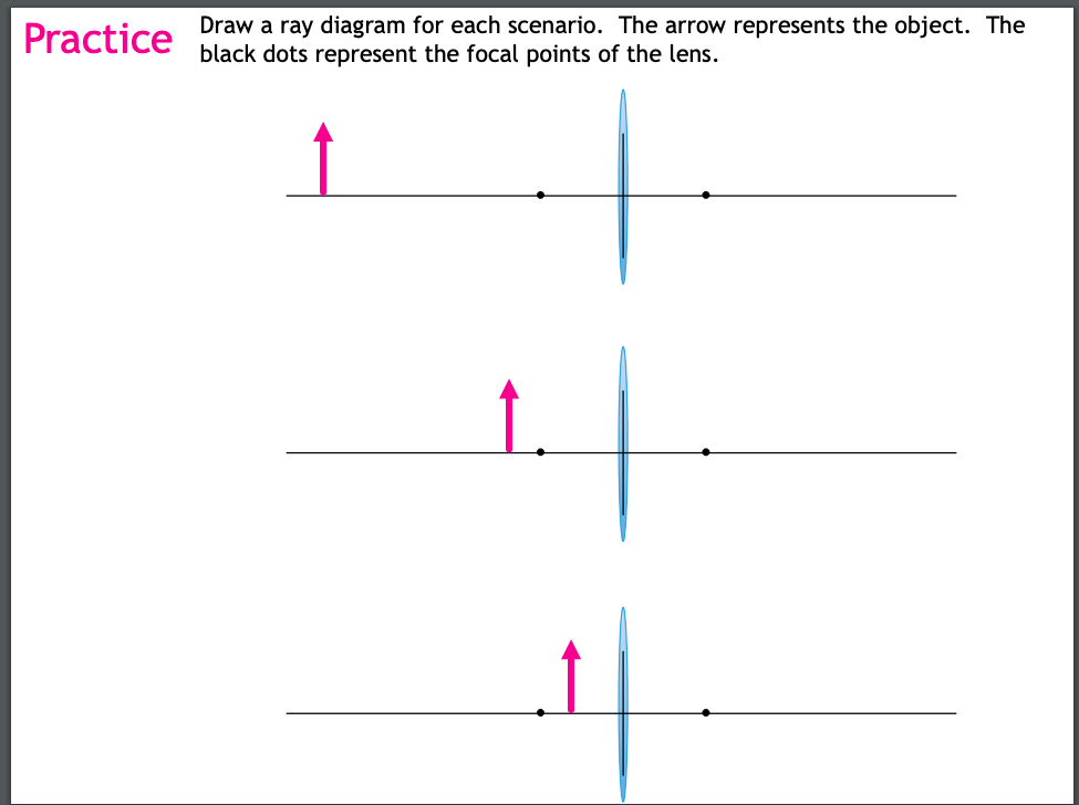
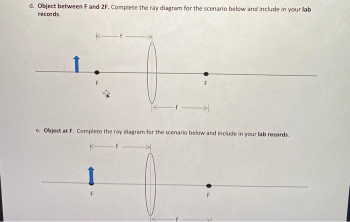
Solved Draw a ray diagram for each scenario. The arrow ...

5.7 Critical angles and total internal reflection ...

q4-draw-a-diagram-showing-the- | LIDO
Ray Diagram PRELAB LAB

CBSE Class 10 Science Practical Skills – Refraction Through ...
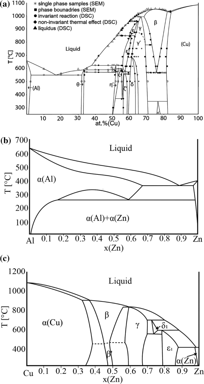
Experimental study of the Al–Cu–Zn ternary phase diagram ...

draw a ray diagram to show the path of the refracted ray in ...
0 Response to "41 draw a ray diagram representing your experiment from part c"
Post a Comment