45 msd power grid wiring diagram
The Power Grid Ignition is MSD's latest digital system, and it features technology In other words, the Power Grid puts all the log screens in one area. The Grid is a great upgrade for those racers who One nifty thing about the setup is the CAN-bus technology reduces the amount of wiring, so for those... [PDF] MSD Power Grid System Controller PN 7730/77303 figure 1 wires of the power grid system controller. figure 2 wiring the power grid. note: see pages lock[PDF] MSD Tech line: (888) 258-3835 WWWOWERSPORTS That is why we have assembled this MSD Ignition Wiring Diagrams and Tech...
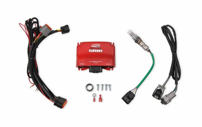
Parts Included: 1 - MSD PowerGrid 7 Ignition Controller 1 - Wire Harness 1 - Parts Bag WARNING: During installation, disconnect the battery cables. the Negative cable first and install it last. Note: Solid core spark plug wires cannot be used with an MSD Ignition Control. The Power Grid 7 Ignition...
Msd power grid wiring diagram
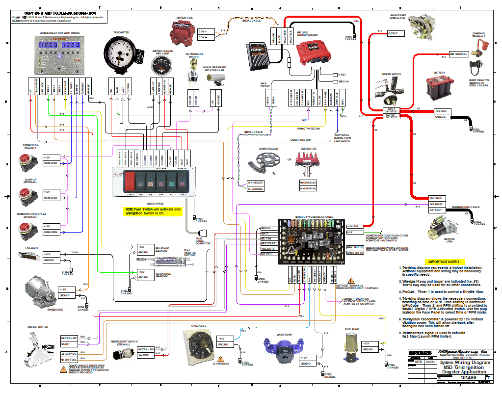
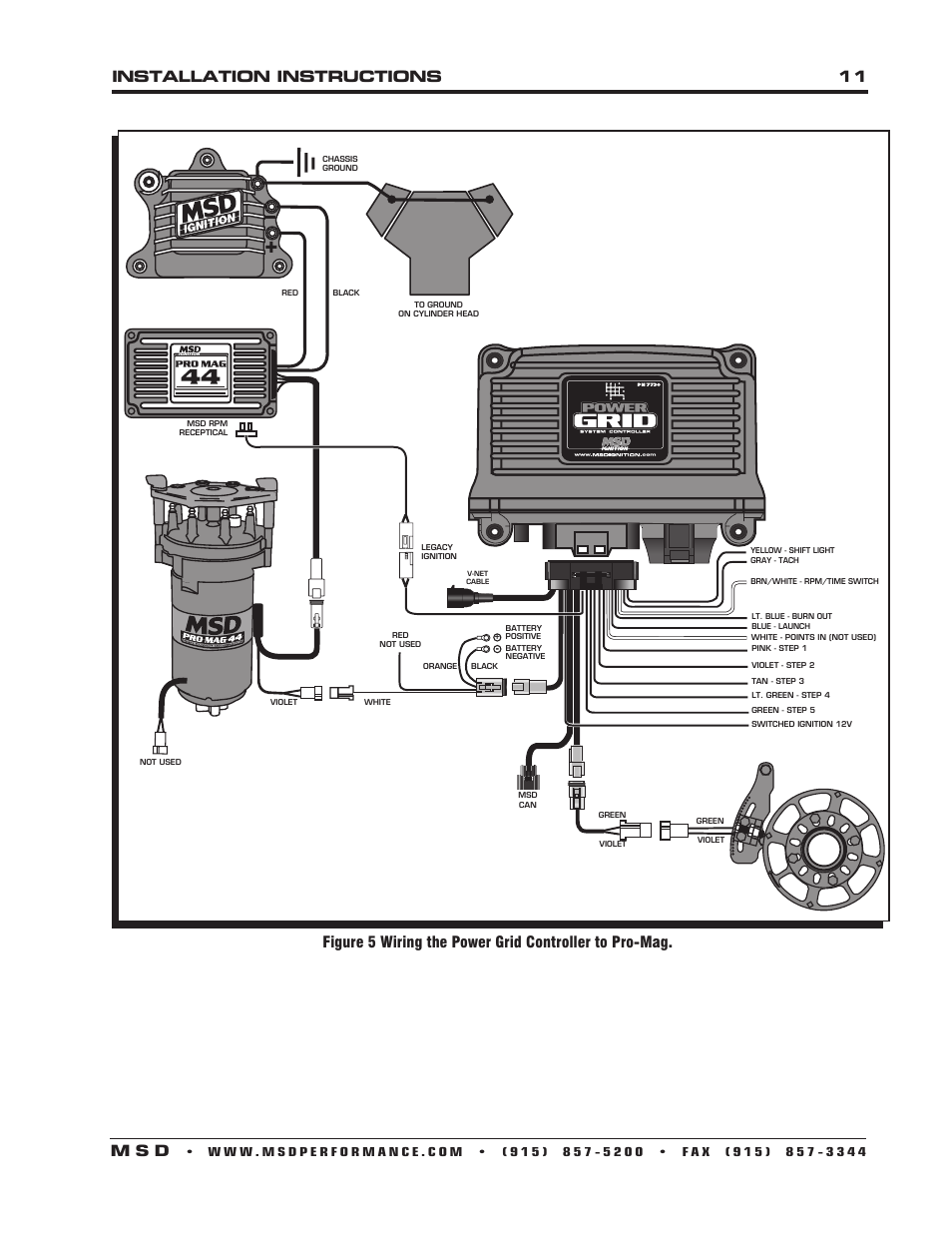
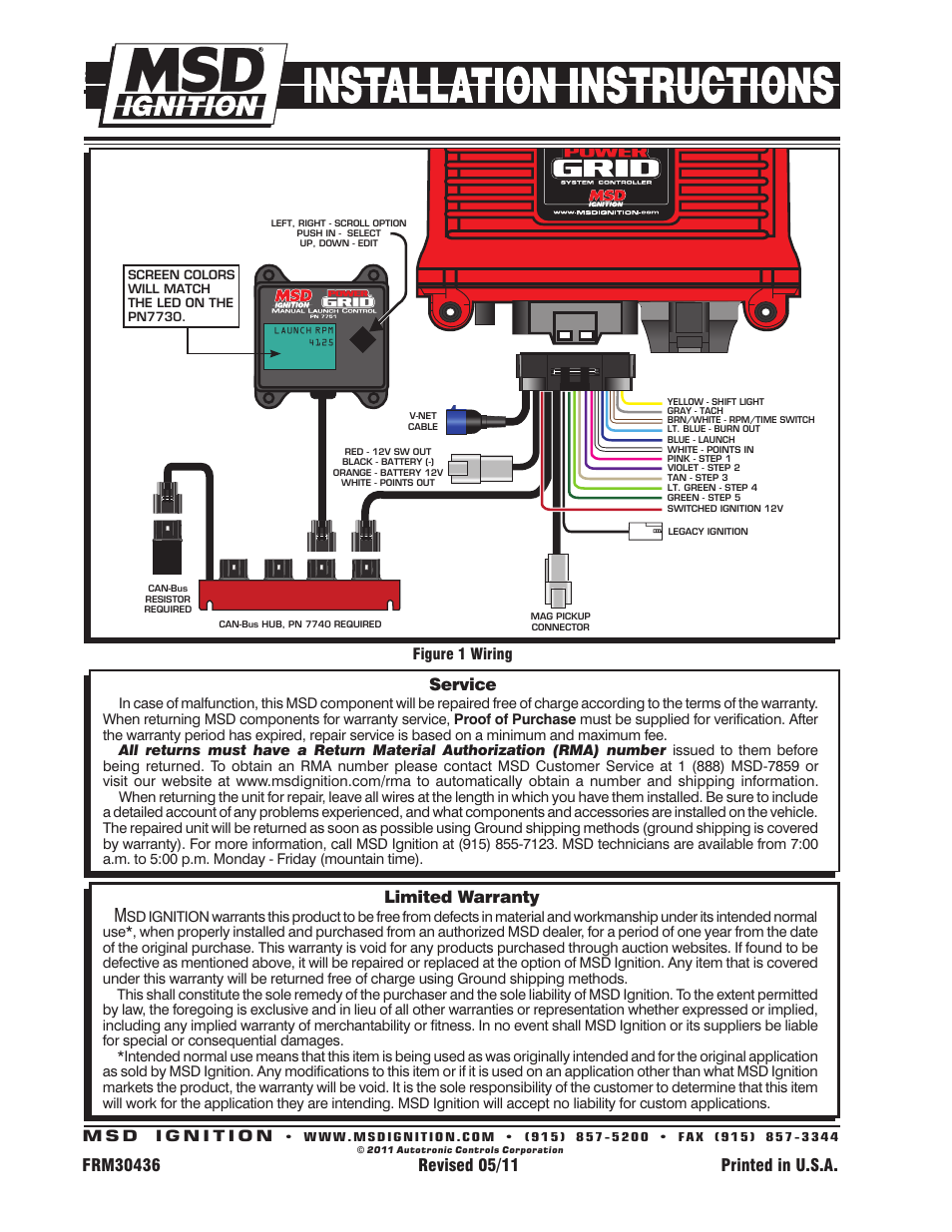
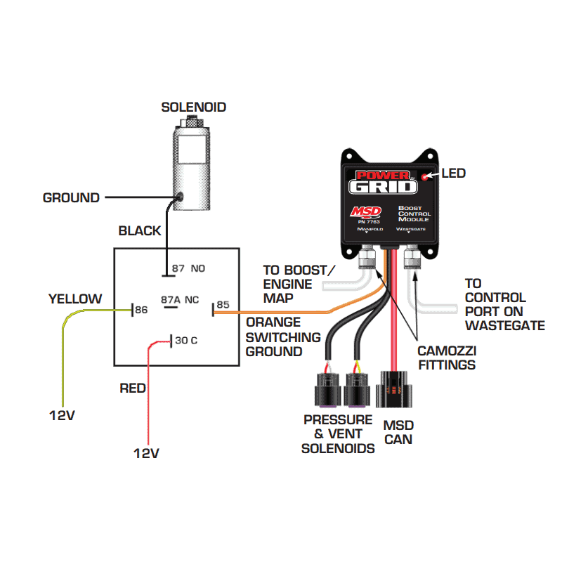
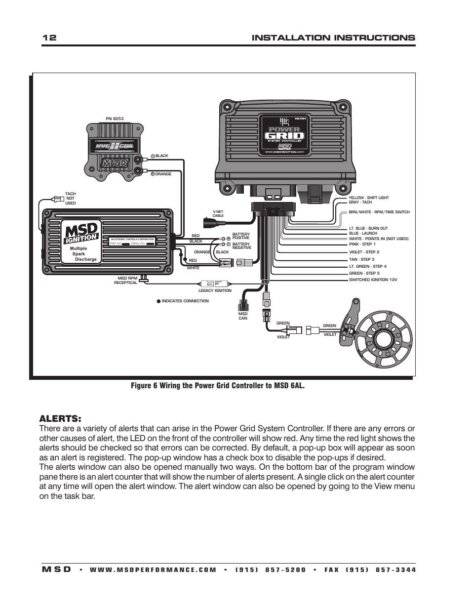
Wiring up the MSD Power Grid is easy to do with this Power Grid wiring schematic. Let's begin with PIN 15, which is a RED wire. Check out the rest of the wiring diagram above and reference it against this list of loose wires that must be connected for the MSD Power Grid. May 7, 2018 - Wiring diagram shows the connection destination for each wire. Note the VNET connection for the Racepak and independent connections for legacy ignitions. All of this is necessary to provide the near unlimited tuning possibilities the Power Grid supplies. LEGACY IGNITION. VNET. ORG - BATT 12y. BLK - BATT-. BED - 12V SW OUT. WHITE - POINTS OUT. CONNECTOR. MAG PICK UP. MSD. C...
Msd power grid wiring diagram. The MSD 6AL Ignition Control set the standards that other ignitions strive to reach. In fact, you'll find ignitions from other companies that carry the 6AL name (and in some cases, the same part number). MSD raised the bar even higher with the revised Digital 6AL Ignition Control! figure 1 wires of the power grid system controller. figure 2 wiring the power grid. note: see pages 10-12 for schematics showing installation to other msd ignition controls. red - 12v sw out black - battery MSD Power Grid Installation Diagram, Eliminates the 7AL or 6AL Box. Published May 30, | By Mike. The Power Grid System Controller, PN 7730 / PN 77303, is designed to be used with the Power Grid-7. Ignition Control, PN 7720. This is a high output CD ignition control. The Ignition System allows for the System. Controller to be mounted on top of the Power Grid-7 to save space and provide a neat, compact installation. Wire Length. The power leads and the wires of the MSD can be short-ened, however the correct connectors should be properly installed and soldered in To indentify which of the following diagrams fit you specific application, remove the distributor cap and rotor and locate the ignition module at the...
Note: Solid core spark plug wires cannot be used with an MSD Ignition Control. Note: A crank trigger is recommended to supply the input signal to the Power Grid Ignition System to PINK 22 STEP 1 Step 1 retard enabled with +12 volt input AND above Step 1 Rpm value OR Gear 2 Select. VIOLET 5 STEP 2 Step 2 retard enabled with +12 volt input AND above Step 2 Rpm value OR Gear 3 Select. TAN 23 STEP3 Step 3 retard enabled with +12 volt input AND above Step 3 Rpm value OR Gear 4 Select. The MSD Power Grid System Controller uses a high speed RISC microcontroller to control the ignition's. output while constantly analyzing the various inputs such as launch, burnout, and step wires; trigger signals, rpm, and CAN-Bus data.The high speed controller can make extremely quick... The Msd Power Grid System Controller Pn 7730 A Wiring Diagram To Connect The Msd Power Grid System Controller To A 6al Can Be Found In The Instructions For The System Controller Pn 7730 A Special Rev Limit Must Be Selected When Feb 2th,
Msd 3 Step Wiring Diagram- wiring diagram is a simplified standard pictorial representation of an electrical circuit. It shows the components of the circuit as simplified shapes, and the capacity and signal contacts amid the devices. A wiring diagram usually gives opinion very nearly the relative... 1 BLACK 22GA CAN LO 2 YELLOW (SLV) 22GA SHIELD 3 BLACK18GAGROUND 4 RED 22GA CAN HI 5 RED 18GA POWER (12V) 6 NOT USED WIRING Power Grid When using the Power Module (PN7764) with the Power Grid (PN7730), connect to the Power Grid via the CAN connector. This increases control options over the outputs and utilizes the Data Recorder. The MSD Power Grid System Controller uses a high speed RISC microcontroller to control the ignition's. output while constantly analyzing the various a built-in Soft Touch Rev Control that uses plug-in RPM modules. Pages 10-12 show wiring diagrams for a. variety of different ignition options. Note: Solid core spark plug wires cannot be used with an MSD Ignition Control. The Power Grid 7 Ignition Control was specifically designed to pair with the Power Grid System Controller, PN 7730. This Ignition system is designed for racing applications; it is not for sale for legal use on highways.
The MSD Power Grid is a versatile timing control that can help solve problems and maintain optimum performance in a variety of racing applications. MSD's versatile Power Grid system was originally conceived when turbo drag cars underwent a wholesale conversion from gasoline to alcohol in search...
Page PN 6201. Power Grid Ignition System. See pages 38 - 40 The evolution of programmable ignition The new Power Grid Ignition System is an advanced programmable ignition and incorporates an all MSD Ignitions install easily to a variety of applications. This diagram shows the wiring with a...
Jun 8, 2019 - This Pin was discovered by Frankie Stark. Discover (and save!) your own Pins on Pinterest
Jun 8, 2019 - This Pin was discovered by Keith Parker. Discover (and save!) your own Pins on Pinterest
The MSD Power Grid System Controller uses a high speed RISC microcontroller to control the ignition's output while constantly analyzing the various inputs such as launch, burnout, and step wires; trigger signals, rpm Pages 10-12 show wiring diagrams for a variety of different ignition options.
Print the electrical wiring diagram off plus use highlighters to be able to trace the routine. When you make use of your finger or perhaps stick to the circuit with your I print the schematic plus highlight the circuit I'm diagnosing to make sure Im staying on the path. Msd Power Grid Wiring Diagram Source...
MSD Power Supply Unit Mechanical installation, Electrical installation, Operation Manual. You will find a wiring diagram, also showing the protective conductor terminals, on page 28. When the MSD Servo Drive DC-AC has been installed as per section 2 and wired with all required voltage supplies...
GENERAL WIRING INFORMATION Wire Length: All of the wires of the MSD Ignition may be shortened as long as quality connectors are used CONNECTING THE DIGITAL 6AL WITH THE MSD POWER GRID SYSTEM CONTROLLER, PN 7730 A wiring diagram to connect the MSD Power...
May 25, 2011 - MSD provides great instructions with respect to the wiring of the PowerGrid. The instructions tell what each wire on every plug powers or monitors, as well as walking the user through the programming and use of each of the many functions that this system provides.
Msd grid wiring diagram. Msd pro mag forum. Unsubscribe from jeff wiebe. In order to use the rev limiting features of the system controller the paired Msd power grid diagram help. Also how and where do i wire in the blue launch grid wire while still using my dedenbear super cross over controller.
*Power Grid Not Updating Online* MSD Power Grid Data Acquisition -video
power coil v. net o elk legacy ignition indicates connection mso green violet yellow - shift light gray tach brn/white • rpm/time switch lt. blue • burn out blue • launch white - points in (not pink - step 1 violet step 2 tan • step a lt. green - step 4 green - step 5 reo ignition green violet .
Crank Trigger To Msd Grid Wiring Diagram. Take your ignition to the next level with the all new MSD Power Grid based on gear or time; Crank Trigger system highly recommended Wiring up the MSD Power Grid is easy to do with this Power Grid wiring schematic. A wiring diagram to connect the MSD Power Grid System Controller to a 6AL can . The LED will flash for every trigger signal from the distributor or crank trigger.
MSD Power Grid Ignition System Data Acquisition Overview Tutorial. Смотреть позже.
Oct 25, 2018 · The MSD Power Grid is a versatile timing control that can help solve Wiring diagram shows the connection destination for each wire. Note the.The Power Grid Controller is the brains behind the entire system and can be used with any MSD Ignition or the Pro Mag to provide advance ignition tuning capabilities. While it is compatible with all MSD boxes, the new Power Grid System Controller has been specially designed to mount to the Power Grid-7 schematron.org: MSD. The Power Grid Ignition is MSD ...
The Power Grid Ignition System is the next evolution of our Programmable 7-Series Ignition Controls. The Grid incorporates an efficient 32 bit microcontroller and an all new software program, called MSD View, and is USB compatible. The Windows based software is designed with tabs to help racers ...
wiring diagram - Diagram Resource 2022 Nov 13, 2021The MSD Power Grid is a versatile timing control that can help solve Wiring diagram shows the connection destination for each wire. Note the Power Grid Controller is the brains behind the entire system and can be used with any MSD Ignition...
[PDF] MSD Power Grid System Controller PN 7730/77303 The System Controller can also be used with other MSD Ignitions such as the 7AL-2 Pages 10-12 show wiring diagrams Related searches for msd grid to 6al wiring diagram msd grid instructionsmsd grid 7730 nos wiringmsd power grid...
The MSD Power Grid is a versatile timing control that can help solve Wiring diagram shows the connection destination for each wire. Note the.The Power Grid Controller is the brains behind the entire system and can be used with any MSD Ignition or the Pro Mag to provide advance ignition...
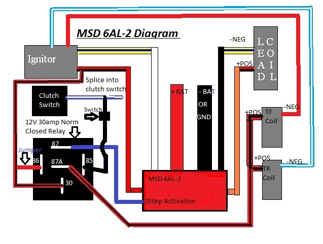
Collection of msd digital 6al wiring diagram. A wiring diagram is a simplified standard pictorial representation of an electrical circuit. It shows the components of the circuit as simplified shapes, and also the power as well as signal connections in between the tools. A wiring diagram generally gives...
Msd grid ignition wiring diagram Msd grid ignition wiring diagram select wiring diagram poised producer poised producer clabattaglia it Msd grid ignition wiring diagram select wiring diagram poised producer poised producer clabattaglia it Msd grid ignition wiring diagram select wiring diagram ...
The Power Grid Controller is the brains behind the entire system and can be used with any MSD Ignition or the Pro Mag to provide advance ignition Spark plug wires. This diagram shows how the CPC Signal Converter wires to a factory coil-per-cylinder ignition to connect a high output DIS-4...
DIGITAL OPERATION The MSD Power Grid System Controller uses a high speed RISC microcontroller to control the ignition's output while constantly analyzing the various inputs such as launch, burnout, and Pages 10-12 show wiring diagrams for a variety of different ignitionoptions.
Wiring Diagrams and Tech Notes. MSD believes that customer service does not end at just producing the best performance components available, helping our The power leads and the wires of the MSD can be shortened, however the correct connectors should be properly installed and soldered in place.
Provides panel wiring diagram and the basics of design and operation. Stand-alone (or off the grid) PV systems are intended to operate independent of the electric utility. Since PV panels do not store energy and can generate electricity only during daylight hours, for continuous power flow they need to...
Msd grid shifter settings. Для просмотра онлайн кликните на видео ⤵. Electric Shifter wiring to MSD 8950Подробнее. Power Grid Basic SetupПодробнее. MSD 7531 Instructional Video 2 Rev Limiters and Step RetardsПодробнее.
You will need to follow the diagram for the Grid 7730 to wire up the 7730, 7720, 8620, 8261 and 84687. Since you have the Dedenbear SCO-1 you can use their diagram on page 3 (Optional Wiring: Nitrous Staging Relay) that way it will activate the nitrous when the trans brake is released.
the Power Grid System Controller so the USB connector and Micro-SD card are accessible. The PN 7730 comes with thread-turning (aka. Self-tapping) screws that will cut into the walls of the pre-drilled holes on the top corners of the Power Grid-7. WIRING GENERAL WIRING INFORMATION Wire Length: All of the wires of the MSD Ignition may
Msd Power Grid Wiring Diagram - schematron Oct 25, 2018The MSD Power Grid is a versatile timing control that can help solve Wiring diagram shows the connection destination for each wire. Note the Power Grid Controller is the brains behind the entire system and can be used with any MSD Ignition...
DIGITAL OPERATION. The MSD Power Grid System Controller uses a high speed RISC microcontroller to control the ignition's output while constantly analyzing the various inputs such as launch, burnout, and Pages 10-12 show wiring diagrams for a variety of different ignition options.
LEGACY IGNITION. VNET. ORG - BATT 12y. BLK - BATT-. BED - 12V SW OUT. WHITE - POINTS OUT. CONNECTOR. MAG PICK UP. MSD. C...
May 7, 2018 - Wiring diagram shows the connection destination for each wire. Note the VNET connection for the Racepak and independent connections for legacy ignitions. All of this is necessary to provide the near unlimited tuning possibilities the Power Grid supplies.
Wiring up the MSD Power Grid is easy to do with this Power Grid wiring schematic. Let's begin with PIN 15, which is a RED wire. Check out the rest of the wiring diagram above and reference it against this list of loose wires that must be connected for the MSD Power Grid.
![MSD Power Grid System Controller PN 7730/77303 - [PDF Document]](https://demo.fdocuments.in/img/378x509/reader024/reader/2021012302/5852cf251a28abfa398e1847/r-2.jpg)







![MSD Power Grid System Controller PN 7730/77303 - [PDF Document]](https://reader024.staticloud.net/reader024/reader/2021012302/5852cf251a28abfa398e1847/html/bg3.png)


0 Response to "45 msd power grid wiring diagram"
Post a Comment