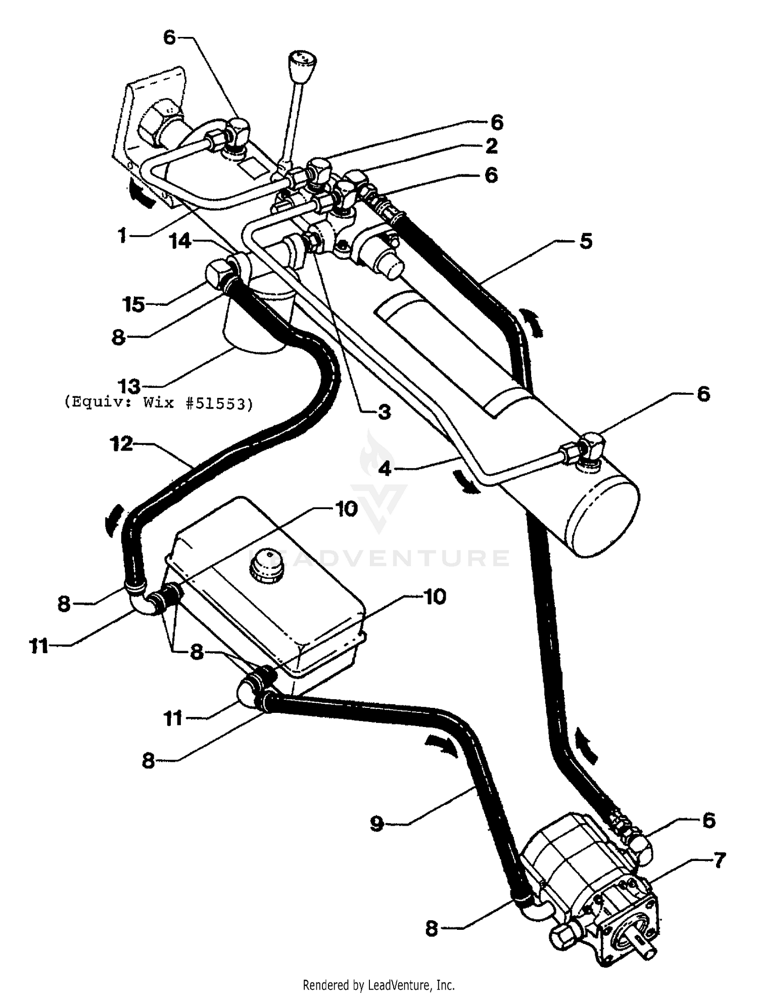
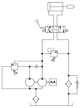
44 log splitter hydraulic diagram
Sep 27, 2016 - Image result for log splitter hydraulic circuit diagram Parts Diagram . ... If you have questions regarding your log splitter, we can ... Parts of the hydraulic circuit (cylinder, pump, valve-.24 pages
model g0639 22-ton hydraulic log splitter -25-parts list ref part # description ref part # description 1 pn03m hex nut m8-1.25 52 plw04m lock washer 8mm 2 pb09m hex bolt m8-1.25 x 20 53 pw01m flat washer 8mm 3 p0639003 piston rod connector 54 pb07m hex bolt m8-1.25 x 25 4 p0639004 front cover connector 55 pb141m hex bolt m12-1.75 x 80

Log splitter hydraulic diagram
Electric Log Splitter Operator's Manual MODEL NUMBER YS0552 SERIAL NUMBER PURCHASE DATE ... Freeing a Jammed Log 9 Replacing Hydraulic Oil 10 ... Plumbing Diagram 11 Parts Diagram 12 Parts List 13 Carefully read through this entire operator's manual before using your new Log Splitter. Pay attention to all cautions and warnings. Engine warranty and contact information is as shown in the engine owners manual. Hydraulic System. 1 Year. Steel Components. 3 Years. Commercial Use. The ...20 pages Northern Hydraulics stocks a variety of hydraulic log splitter replacement parts, accessories, and engines to get your unit running smoothly. Call 1-800-823-4937 for information on choosing the hydraulic log splitter pumps, valves or cylinders that are right for you.
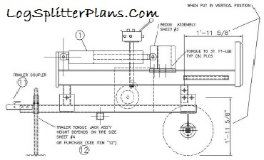
Log splitter hydraulic diagram. Power Equipment log splitter . CPE designs and builds log splitters to strict specifications . With proper use and maintenance, this log splitter will bring years of satisfying service . Portable Log Splitter This unit is a gasoline engine driven hydraulic log splitter . It is designed to split wood logs for use as fire wood for a stove or fire ... The hydraulic system of your log splitter requires careful inspection along with the mechanical parts. Be sure to replace frayed, kinked, cracked or otherwise damaged hydraulic hose and components. ... STEP 2: Attach the tongue (3) to the tank/axle (2) as shown in the diagram using the two 1/2 in. NC x 4-1/2 in. hex cap screws (75), 1/2 in. ONLY operate the log splitter from the operator zone as shown in the diagram. Operating the log splitter in another location can result in serious injury or death. • ALWAYS chock the wheels to prevent movement of the log splitter while in operation. • KNOW how to stop the log splitter and disengage the controls before operating it. Log Splitter Detent Valve Diagram The USA's most popular log splitter valve. Specified by Spring centered in one direction, and pressure released detent in the other direction. Automatically. The detent valve in a log splitter is the central assembly where the the diagram will show you which ones go on which side of the detent valve.
Gas Log Splitter Operator's Manual ... Assembly 12 Parts Diagram 25 ... Pay attention to all cautions and warnings. This unit is a gasoline engine driven hydraulic log splitter. It is designed to split wood logs for use as firewood for a stove or fireplace. This log splitter will only split logs lengthwise with the grain. 1 Find the diagram. Find the diagram of the detent valve set up. There will be input valves for the pressurized and un-pressurized hose connections, and the diagram will show you which ones go on which side of the detent valve and in what order. If the hydraulic hoses are hooked up incorrectly, then the valve won't be able to function properly. We carry replacement hydraulic cylinders, hoses, fittings, pumps, as well as new wedges and accessories for your log splitter. We supply log splitter parts for the biggest brands, including Ariens, Gravely, MTD, and Troy-Bilt. Select a category below, or use our Log Splitter Parts Lookup with exploded parts diagrams. Huskee Log Splitters Parts Lookup & Diagrams Huskee Log Splitters ( 2 Models ) 24BA560C131 - Huskee Log Splitter (1999) (Tractor Supply) 24BA560C131 - Huskee Log Splitter (2000) (Tractor Supply) This model has more than one variation. Select one: The Right Parts, Shipped Fast!
The Log Splitter Hydraulic Circuit. Most log splitters use a hydraulic cylinder ( like these) to push a cut piece of log into a sharpened wedge, which splits it. The cylinder is driven by hydraulic oil, under pressure, produced by a hydraulic pump. An engine, or electric motor, drives the pump shaft, and supplies the power for the system. Hydraulic Oil Reservoir Log Splitter Valve Auto Cycle Valve . Open Center hydraulic Valve: There are two basic valve systems used on log splitters: They come with different options . 1-Log splitter valve - You have to hold the valve lever on the splitting stroke & on the return stroke, there is a detent to Log Splitter Hydraulic Troubleshooting 9 - 17 2. With the log splitter off, cycle the control valve forward and rearward several times to relieve any pressure in the hydraulic system._____ See Figure 2. 3. Remove the high pressure hydraulic hose from the inlet port of the control valve using channel locks and a (1 and 1/8") wrench._____ The hydraulic cylinder as it the backbone of any hydraulic log splitter. Its force the log into a metal wedge to split it into pieces (see splitting wedge heads). These hydraulic cylinders can be mixed and matched to the pump and power source but the hydraulic cylinder tonnage rating must not be below the hydraulic pump tonnage rating.
The diagram shows a winch powered by a hydraulic motor. The directional control valve with built-in relief features optional flow control to control the speed of the winch . The hydraulic pump and motor must be matched to the torque requirements of the winch. Logsplitter.
The hydraulic oil pump creates a stream of high-pressure oil, which runs to a valve. The valve lets the operator actuate the hydraulic cylinder to split a log. There is also a tank to hold the hydraulic oil that feeds the pump and usually a filter to keep the oil clean. Valves can apply both forward and backward pressure to the piston.
Hydraulic pumps for log splitters usually are either a single-stage or a two-stage pump. Cheaper, often off-brand log splitters, and even some larger well-known commercial log splitters may come with a single-stage pump. A single stage pump will do the task, but it moves the hydraulic cylinder slower. Splitting time is increased.
Directional control valve - Log splitter Model P81 ... 1 0 2 Hydraulic scheme for P81 A2 S10 2/7 Sep 2013. Port type (S - UN-UNF, G - BSP, N-NPTF) Spool detent - detent with hydraulic release (70 to 140 bar) Spool type (A) Directional control valve (80 l/min) Order Code: P81 A 2 G 12
Engine Parts Diagram . ... This unit is a gasoline engine driven hydraulic log splitter . ... Parts of the hydraulic circuit (cylinder, pump, valve-.30 pages
Item# S47021300. Protect your investment -- keep your log splitter clean, dry and ready to use! SpeeCo's log splitter cover is manufactured with PVC coated polyester to shield from water, UV, mildew and cold temperatures. Snaps to keep cover secure on log splitter. Fits 22-35 Ton log splitters. Available in black.
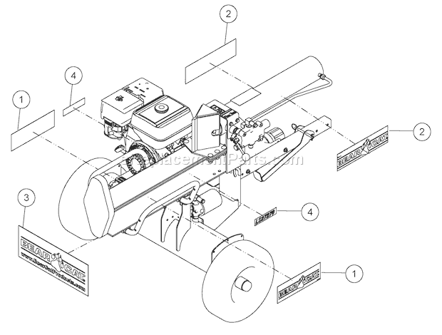
Foards Parts Plus offers a complete collection of replacement parts for Speeco 25- and 28-ton log splitters (597477, 597478). Explore the diagram online.
I need a hydraulics diagram for building my own wood splitter, it will have two cylinders, one for splitting and one for a lifting tray to lift bigger pieces onto the splitter. the hydraulic pump I got has three ports one large port that comes from the oil reservoir [ this I know ] and the two other smaller ports are located on either side of the larger port. are these smaller ports pressure ...
Description : Speeco S390406Sc Log Splitter Valve - Omni Mfg Llc with regard to Huskee Log Splitter Parts Diagram, image size 500 X 380 px, and to view image details please click the image. Here is a picture gallery about huskee log splitter parts diagram complete with the description of the image, please find the image you need.
Most commercially available log splitters use a hi-lo pump, which is essentially two pumps in one — a high-pressure, low-flow pump and a low-pressure, high-flow pump operating in tandem. In normal operation, both pumps route fluid to the cap end of a cylinder. When a wedge mounted to the cylinder's rod end engages the log, system pressure ...
ONLY operate the log splitter from the operator zone as shown in the diagram. The operator has the safest and most ... The hydraulic system of your log splitter requires careful inspection along with the mechanical parts. Be sure to replace frayed, kinked, cracked or otherwise damaged hydraulic hoses or hydraulic components. ...
The hydraulic system of your log splitter requires careful inspection along with the mechanical parts. Be sure to replace frayed, kinked, cracked or otherwise damaged hydraulic hose and components. ... STEP 2: Attach the tongue (3) to the tank/axle (2) as shown in the diagram using the two 1/2 in. NC x 4-1/2 in. hex cap screws (48), 1/2 in.
Didier log splitter parts results for didier log splitter parts filter by: We hope it helps solve your problem. Log splitter replacement parts refine search. 1981 kz650 wiring diagram, carprog opel ecu manual, 1967 pontiac gto le mans tempest wiring diagram, the lawman s second. If you have a leaky hydraulic hose or broken cylinder, the power ...
Log Splitter Valves. Find Original Equipment hydraulic valves for all log splitter applications. Original replacemet valves all 20-ton, 22-ton, 25-ton, 27-ton and 33-ton models. For Troy-Bilt, Craftsman, MTD, Cub Cadet, Yard-Man, Huskee, Yard Machines and Bolens Log splitter Models, shipped Factory-Direct. 5 Results.
Northern Hydraulics stocks a variety of hydraulic log splitter replacement parts, accessories, and engines to get your unit running smoothly. Call 1-800-823-4937 for information on choosing the hydraulic log splitter pumps, valves or cylinders that are right for you.
Engine warranty and contact information is as shown in the engine owners manual. Hydraulic System. 1 Year. Steel Components. 3 Years. Commercial Use. The ...20 pages
Electric Log Splitter Operator's Manual MODEL NUMBER YS0552 SERIAL NUMBER PURCHASE DATE ... Freeing a Jammed Log 9 Replacing Hydraulic Oil 10 ... Plumbing Diagram 11 Parts Diagram 12 Parts List 13 Carefully read through this entire operator's manual before using your new Log Splitter. Pay attention to all cautions and warnings.

Magister Hydraulics Log Splitter Hydraulic Cylinder - Universal Hydraulic Cylinder 4" Bore 24 inch Stroke - Heavy Duty Hydraulic Cylinders (4x24)




_WW_1.gif)







0 Response to "44 log splitter hydraulic diagram"
Post a Comment