44 ignition coil wiring diagram ford
May 28, 2020 · Ford Ignition Coil Wiring Diagram from i135.photobucket.com. To properly read a cabling diagram, one provides to know how typically the components within the program operate. For example , when a module is usually powered up also it sends out the signal of fifty percent the voltage and the technician does not know this, he'd think he offers a ... Explanation of how the ignition system of a car works in an automobile. Discover how the current goes through the coil to the sparkplug. Automotive electrical systems have grown more complex over the years, but the basic principles behind them are similar. The alternator or generator will power the car while recharging the battery at the same time.
About Ford Wiring • Wires were cloth covered, rubber insulated • Ford used 16 gauge wire on lamp wiring • Wire gauges in 1930’s not the same as today • Wires were bigger around, yet not as good – Modern materials – Better copper stands • 6 Volt systems need a larger gauge than 12 volt to ensure good current flow
Ignition coil wiring diagram ford
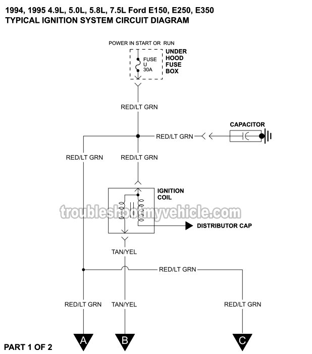
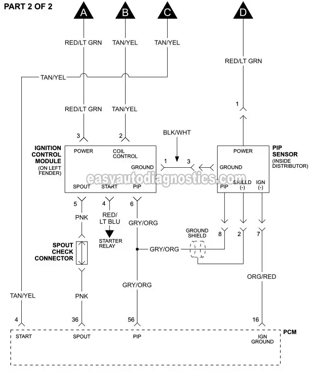
Ignition Coil. Ignition Control Module (ICM). Profile Ignition Pickup (PIP) Sensor. You can find the ignition system wiring diagram for the 1994-1995 Ford E150 (E250, E35) here: Ignition System Wiring Diagram (1994-1995 Ford E150, E250, E350). Ignition System Wiring Diagram (1996 Ford E150, E250, E350). This fuel pump circuit wiring diagram includes the following circuits: Ignition Coil. Ignition Control Module (ICM). Profile Ignition Pickup (PIP) Sensor. You can find the ignition system wiring diagrams for the 1992-1995 Ford E150 (E250, E35) here: Ignition System Wiring Diagram (1992-1993 Ford E150, E250, E350). Briggs & Stratton ignition coil wiring diagram related problems. 721 725 718d 721d. On the other hand, this diagram is a simplified variant of the arrangement. If you need a Briggs and Stratton ignition coil, solid state ignition module, voltage regulator, condenser, ignition set, or any other parts for the ignition system of your Briggs and ...
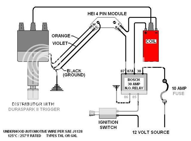
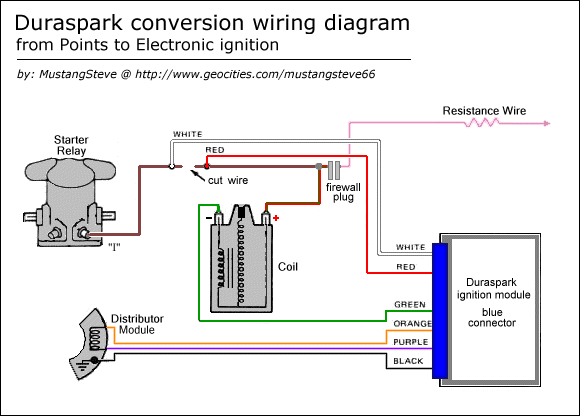
Ignition coil wiring diagram ford. Basic points ignition wiring diagram wiring diagram is a simplified satisfactory pictorial representation of an electrical circuit it shows the components of the circuit as simplified shapes and the power and signal connections between the devices. If used for 6 volt make all the wires heavier by 2 gauges. Follow the wiring instructions included with the new solenoid. Run a section of 18-gauge wire from the "I" terminal on the starter to the "+" terminal on the ignition coil. Strip 1/4 inch of wire from the end of the wire using the wire strippers and then crimp a blue ring terminal on each end. Then connect the wiring to the terminals ... Part 1 ford ignition system circuit diagram 1992 1993 f150 f250 f350 1994 1995 wiring e150 e250 e350 duraspark ii the v 8 engine work diagrams coil truck enthusiasts forums 1997 1999 4 6l mercury lincoln electronic control module unit connections with a magnetic pickup what distributor and fits early 1974 390 classic inlines which is better Your original wiring shown below from the Ford Service Manual. Once that is done, you really need to figure-out what that extra wire goes to, so whatever it is remains working, or doesn't create a problem. The wires to your alternator in the charging and starting system are also shown below. David F falconfred Registered Joined Apr 2, 2014
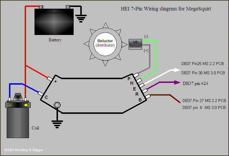
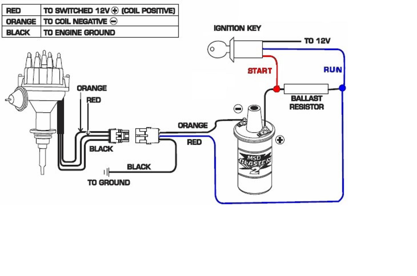
Wiring diagram for ignition coil more information find this pin and more on 63 f100 wiring by ben platt. This applies to all old cub cadet ford jacobsen john deere wheel horse case and simplicity garden tractors. We did our best to keep this as simple and as easy to understand as possible. According to earlier, the traces in a Ignition Coil Wiring Diagram represents wires. Occasionally, the wires will cross. However, it doesn't mean link between the cables. Injunction of two wires is usually indicated by black dot to the intersection of two lines. There'll be primary lines that are represented by L1, L2, L3, and so on. Description : Wiring Diagram For Ignition System Ignition System Wiring Diagram throughout Ignition Coil Wiring Diagram, image size 1146 X 344 px, and to view image details please click the image. Here is a picture gallery about ignition coil wiring diagram complete with the description of the image, please find the image you need. Ignition Coil Wiring Diagram Ford from easyautodiagnostics.com Print the wiring diagram off plus use highlighters to trace the signal. When you make use of your finger or perhaps the actual circuit with your eyes, it is easy to mistrace the circuit. 1 trick that We 2 to printing a similar wiring plan off twice.
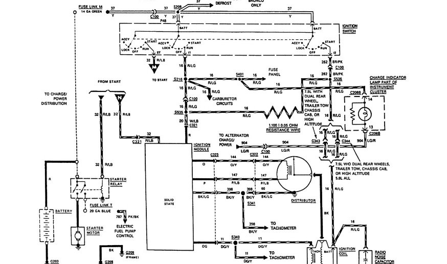
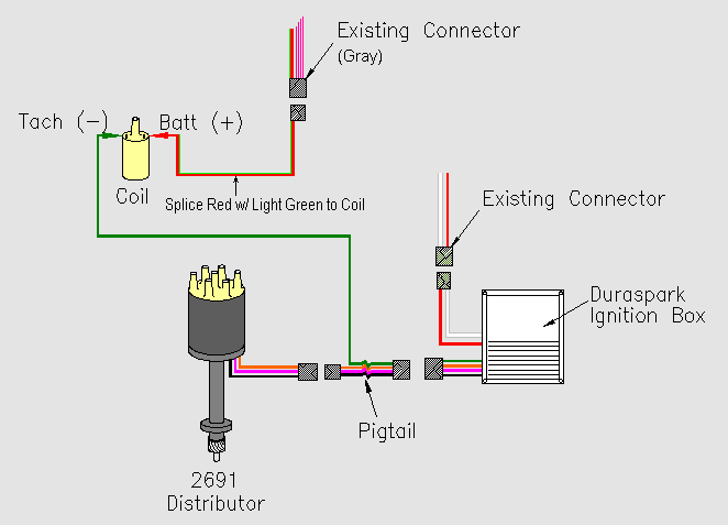
The wiring diagram shown below was obtained from Pertronix to show the proper hookup for a Pertronix. ... from your electronic pickup in your distributor between the black and red wires they must be unplugged from the coil/msd to check.Pertronix Ignition Wiring Diagram | Wiring LibraryModel 'A' Ford Garage ~ Model 'B' Ford Garage. Ford 221 260 289 302 pro series 66 galaxy 500 automobiles no ignition switch hotwire attempt wiring diagram 4 electronic pertronix ignitor and coil 1968 mustang coupe hei distributor 1966 diagrams average question duraspark 2 conversion full automotif for ranger ii basics Duraspark II Ignition Harness connect the components in Ford electronic ignition systems using the in the diagram, a wire from the ignition switch .Sep 25, · A DURASPARK II setup requires full BAT VLT to the module (keyed through IGN SW) and if using a DURASPARK II coil, it (coil) must be run through a resistor. According to earlier, the traces in a Ford Ignition Control Module Wiring Diagram represents wires. Sometimes, the wires will cross. However, it does not mean link between the cables. Injunction of two wires is usually indicated by black dot on the intersection of 2 lines. There will be main lines that are represented by L1, L2, L3, and so on.
The ignition coils are listed from 'A" to "L" (up to 12 cylinders) and they are in sequence according to the firing order.
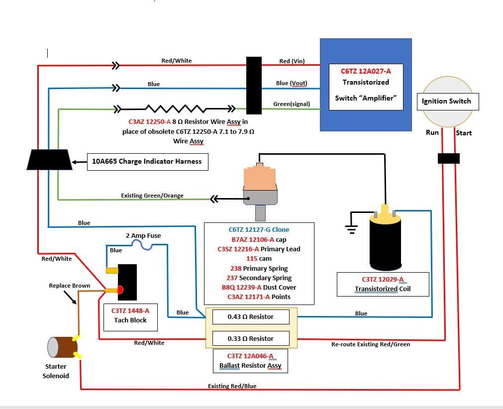
1961 - 1966 F-100 & Larger F-Series Trucks - Ignition Coil Wiring Diagram - Before I start splitting open electrical tape, can someone post a wiring diagram that includes the ignition switch, ignition coil, and starter solenoid? For reference, this is a 1966 352FE. Specifically, I'm looking for a resistor ignition...
The first place that you would want to start looking for what could be causing P0351 in your vehicle would be the wiring harness. You can use a digital voltmeter to check if the coil pack is getting the proper signal. You would want to set it for A/C hertz and check to see if it is between 5-20hz.
Dec 10 2016 automotive wiring diagram resistor to coil connect to distributor wiring diagram for ignition coil. The ignition coil consists of two coils of wire primary and secondary within the plastic housing. One wire called the secondary is made up of thousands more windings than the other one called the primary. Diagnostic manual comes with.
Mar 13, 2018 · Ignition System Wiring Diagram (1994-1995 Ford E150, E250, E350) (at: troubleshootmyvehicle.com). The PIP (Profile Ignition Pickup) is the defacto crankshaft position sensor and is located inside the distributor (although in the wiring diagram it's not illustrated as so).
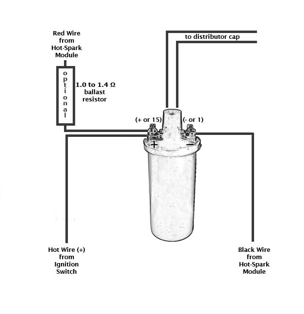
Diagram attached for wiring of points dizzy and coil with ballast resistor. This simple system is easy for even the novice mechanic to wire. A resistor that has the property of increasing in resistance as current flowing through it increases and decreasing in resistance as current decreases. Discussion in 1960 1966 started by ol betsy dec 20 2006.
Wiring Diagram Of Ignition Coil On A 04 Ford Mustang 3.9. RockAuto ships auto parts and body parts from over manufacturers to customers' doors worldwide, all at warehouse prices. Easy to use parts catalog. Here's a diagram for V6 Ford firing order removal and installation instructions, illustrations, wiring diagrams, component locations, torque.
This simplified ignition system wiring diagram applies to the following vehicles: 1992, 1993 (4.9L, 5.0L, 5.8L, 7.5L) F150, F250, and F350. 1992, 1993 (4.9L, 5.0L, 5.8L) Bronco.
Ford Wiring Diagrams By Michael | December 14, 2018 6 Comments See also: Here are wiring diagrams for Ford Escort, F-series, Fiesta, Focus, Mustang, Ranger, Kuga and Many other's. Post navigation ← Ford Workshop Repair Manual Mazda 2 Workshop & Owner's Manuals →
Wiring diagram for 1951 COE Truck. Wiring diagram for 1953-55 Truck. Wiring Schematics - Mercury. (showing the electrical path and connections) Wiring for 1939 Mercury. Wiring for 1940 Mercury. Wiring for 1941 Mercury. Wiring for 1942 Mercury. Wiring for 1946 to 48 Mercury.
Jul 31, 2021 · Ford Ignition Coil Wiring Diagram wiring diagram is a simplified enjoyable pictorial representation of an electrical circuit. Basic ignition system wiring diagram. 1995 Ford F150 Ignition Wiring Diagram To properly read a cabling diagram one offers to find out how the particular components inside the system operate.
Insert into the coil wires. Make sure they are properly earthed on the engine. Crank the motor and check for spark at each of the plugs. Refer to the diagram. Cylinders are connected as shown on the diagram in blue. 1 goes to cylinder 1 (sparkplug furthest from coil pack), 2 to 2, 3 to 3 and 4 to 4 (closets to coil pack).
Briggs & Stratton ignition coil wiring diagram related problems. 721 725 718d 721d. On the other hand, this diagram is a simplified variant of the arrangement. If you need a Briggs and Stratton ignition coil, solid state ignition module, voltage regulator, condenser, ignition set, or any other parts for the ignition system of your Briggs and ...
This fuel pump circuit wiring diagram includes the following circuits: Ignition Coil. Ignition Control Module (ICM). Profile Ignition Pickup (PIP) Sensor. You can find the ignition system wiring diagrams for the 1992-1995 Ford E150 (E250, E35) here: Ignition System Wiring Diagram (1992-1993 Ford E150, E250, E350).
Ignition Coil. Ignition Control Module (ICM). Profile Ignition Pickup (PIP) Sensor. You can find the ignition system wiring diagram for the 1994-1995 Ford E150 (E250, E35) here: Ignition System Wiring Diagram (1994-1995 Ford E150, E250, E350). Ignition System Wiring Diagram (1996 Ford E150, E250, E350).












0 Response to "44 ignition coil wiring diagram ford"
Post a Comment