41 honeywell rth8500d wiring diagram
manualzz.com › doc › enHoneywell RTH8500D Installation guide | Manualzz View online(60 pages) or download PDF(1.78 MB) Honeywell RTH8500D Instructions / Assembly • RTH8500D thermostats pdf manual download and more Honeywell online manuals schematron.org › honeywell-rth8500d-wiring-diagramHoneywell Rth8500d Wiring Diagram - schematron.org Honeywell Rth8500d Wiring Diagram. 24.11.2018 24.11.2018 2 Comments on Honeywell Rth8500d Wiring Diagram. View and Download Honeywell RTHD owner's manual online.
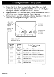
› manual › 675141HONEYWELL RTH8500 SERIES QUICK INSTALLATION MANUAL Pdf ... Advanced Installation Guide About your new thermostat Wiring—heat pump Connect wires: Heat Pump 1. Match each labeled wire with same letter on new thermostat. 2. Use a screwdriver to loosen screws, insert wires into hole, then tighten screws. 3. If E and Aux do not each have a wire connected, use a small piece of wire to connect them to each ...
Honeywell rth8500d wiring diagram
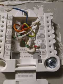
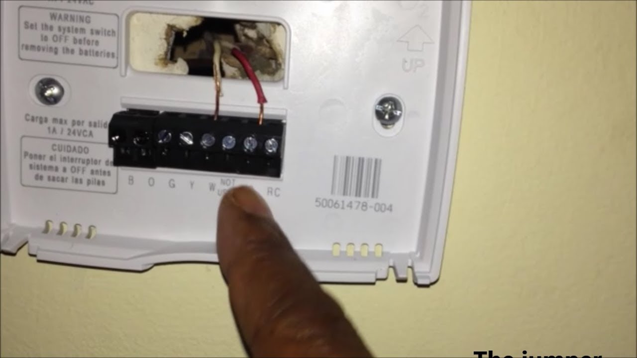
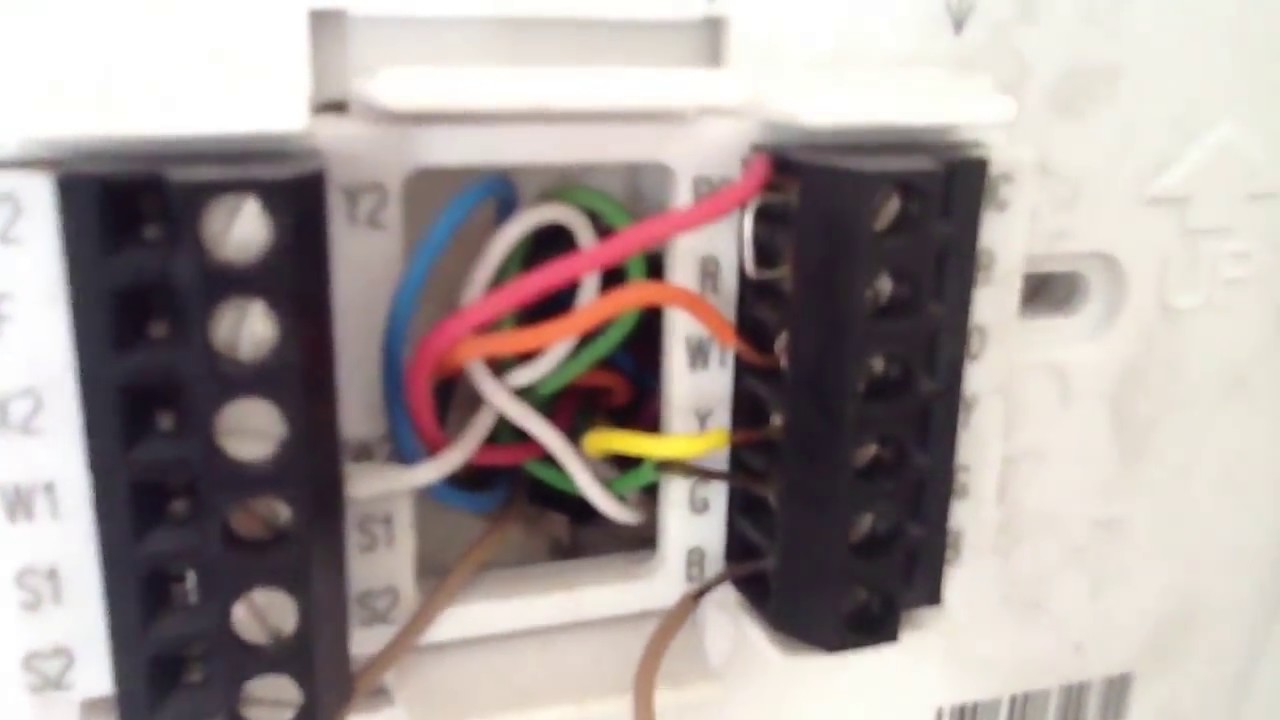
customer.honeywell.com › resources › techlit69-1902EF-1 - RTH8500 - Honeywell the R wire to the Rc terminal, and the RH wire to the R terminal. If your old thermostat had only 1 C or C1 wire, connect it to the C terminal. If your old thermostat had 2 C or C1 wires, wrap each separately with electrical tape and do not connect them. Alternate wiring (conventional systems) RC R W Y G C Y2 W2 Rc R W Y G C Y2 W2 2 3 2 › us › enHow do I wire my RTH8500WF WiFi Series WiFi ... - Honeywell Home Nov 03, 2020 · Wiring Details: The thermostat uses 1 wire to control each of your HVAC system’s primary functions, such as heating, cooling, fan, etc. See the diagram below for what each wire controls on your system: Y – Compressor Stage 1 (Cooling) Y2 – Compressor Stage 2 (Cooling) G – Fan. C – Common.
Honeywell rth8500d wiring diagram. › us › enHow do I wire my RTH8500WF WiFi Series WiFi ... - Honeywell Home Nov 03, 2020 · Wiring Details: The thermostat uses 1 wire to control each of your HVAC system’s primary functions, such as heating, cooling, fan, etc. See the diagram below for what each wire controls on your system: Y – Compressor Stage 1 (Cooling) Y2 – Compressor Stage 2 (Cooling) G – Fan. C – Common. customer.honeywell.com › resources › techlit69-1902EF-1 - RTH8500 - Honeywell the R wire to the Rc terminal, and the RH wire to the R terminal. If your old thermostat had only 1 C or C1 wire, connect it to the C terminal. If your old thermostat had 2 C or C1 wires, wrap each separately with electrical tape and do not connect them. Alternate wiring (conventional systems) RC R W Y G C Y2 W2 Rc R W Y G C Y2 W2 2 3 2
RTH8500 Wiring O and B Terminals | DIY Home Improvement Forum
wiring help

Automation design - solutionberry
RTH8500D Advanced Setup - Honeywell 7 Day Touchscreen ...

Honeywell Vision PRO 8000 Touchscreen Programmable Thermostat ...

20 Best Honeywell Programmable Thermostat ideas ...

Dual Heat Pump System not cooling : r/Nest

Honeywell RTH8500D User Manual
Wiring Honeywell rth8500

RTH8500D Wiring - Honeywell 7 Day Touchscreen Universal ...

Installation Questions - is the blue at the thermostat a C ...

How to Install a WiFi Thermostat without a C Wire | Updated ...

I have this same heat pump with ac and Im trying to setup a ...

Honeywell Thermostat Wiring Color Code - Tom's Tek Stop

replaced CT-100z-wave with Honeywell RTH8500 and it didn't ...
Manual Honeywell RTH8500D (page 57 of 64) (English)
RTH8500 Wiring O and B Terminals | DIY Home Improvement Forum

Help Wiring for RTH8500D from T6575C - DoItYourself.com ...

Manual Honeywell RTH8500D (page 57 of 64) (English)

Ecobee Wiring - Album on Imgur

Honeywell Thermostat RTH8580WF & C Wire Installation Part 2
Thermostat Wiring Question w/ Pics - DoItYourself.com ...
2-Wire Installation for Honeywell Thermostat
honeywell rth8500d1013 installation manual

How to Install a WiFi Thermostat without a C Wire | Updated ...
honeywell thermostat manuel
Heat Pump Operation & Thermostat Wiring

honeywell rth8500d1013 installation manual

Honeywell RTH8500D Temperature Calibration : r/HVAC

Honeywell T5 7-Day Programmable Thermostat (RTH7560E1001) for ...

Am I compatible to upgrade to Nest? I am wondering what the ...
HONEYWELL RTH6300B INSTALLATION MANUAL Pdf Download | ManualsLib
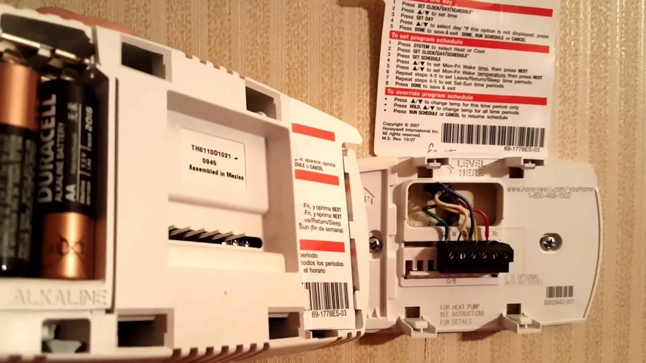
Honeywell Thermostat Battery Replacement | How To Change Batteries

Installing honeywell RTH8500 thermostat only blows cold air ...

T5 7-Day Programmable Thermostat - Shop Now | Honeywell Home

Honeywell Vision PRO 8000 Touchscreen Programmable Thermostat ...

How Wire a Honeywell Room Thermostat Honeywell Thermostat ...

Want to upgrade Thermostat, but can't : r/HomeImprovement

Honeywell RTH8500 Series Manuals | ManualsLib

Honeywell TH8110U1003 Vision Pro 8000 Thermostat for sale ...

Please help me debug my nest thermostat (2nd gen) setup : r/Nest
0 Response to "41 honeywell rth8500d wiring diagram"
Post a Comment