45 mercury stator wiring diagram
Jun 16, 2020 · Mercury Stator Wiring Diagram– wiring diagram is a simplified standard pictorial representation of an electrical circuit.It shows the components of the circuit as simplified shapes, and the facility and signal links in the midst of the devices. Dec 22, 2021 - Key Switch Wire Diagram for A Mercury Outboaed with Chock . Key Switch Wire Diagram for A Mercury Outboaed with Chock . Mercury Outboard Wiring Diagram. Bbaeecc 40 Hp Mercury Outboard Starter solenoid Wiring. 8d160a2 40 Hp Mercury Outboard Starter solenoid Wiring
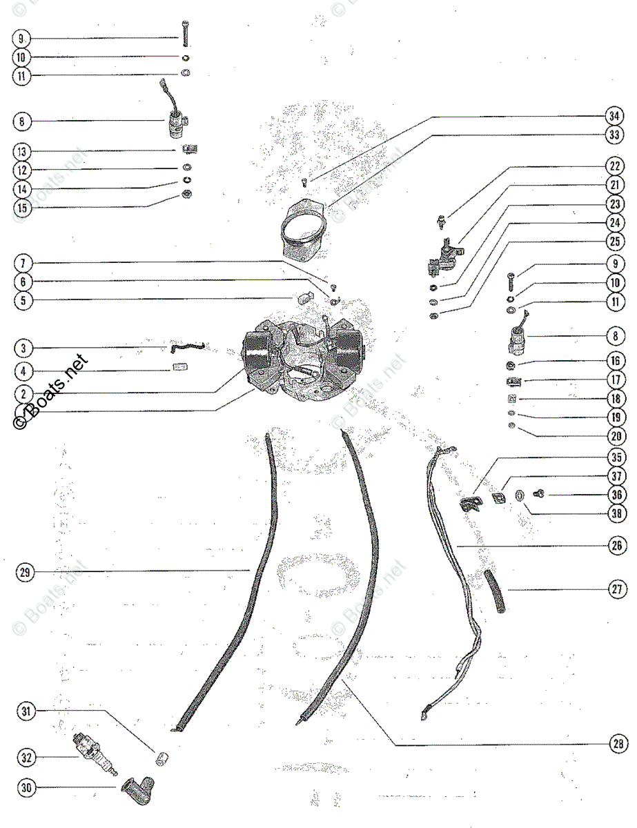
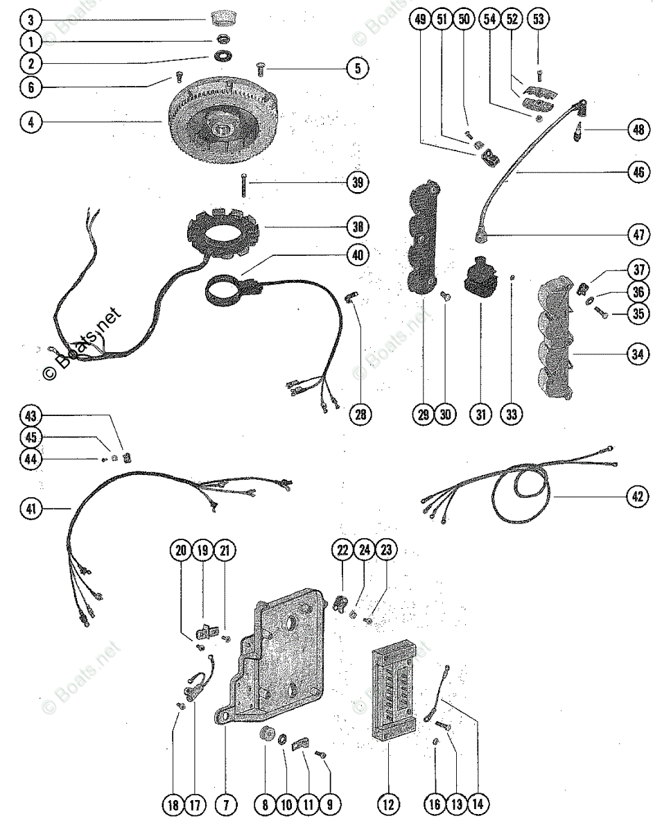
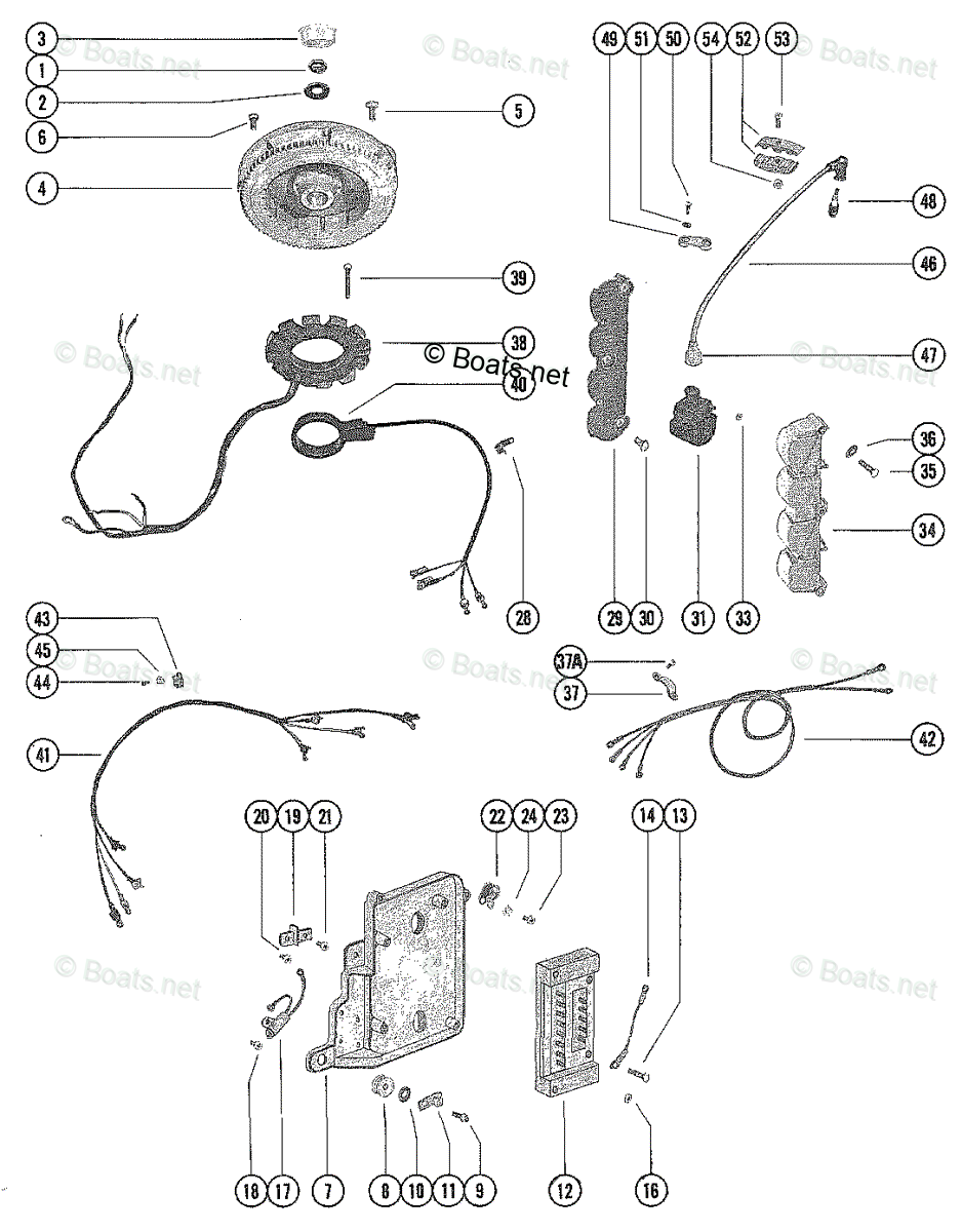
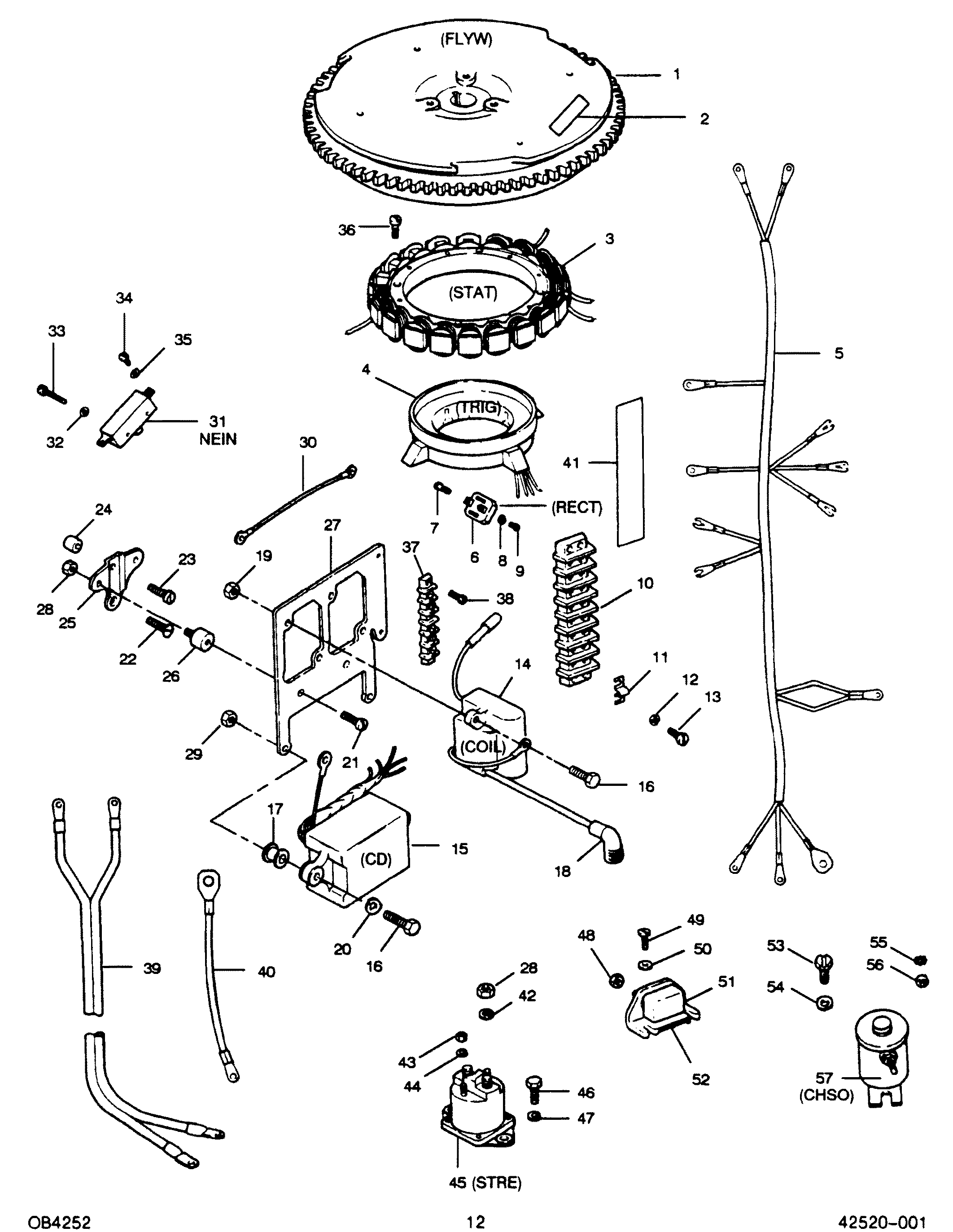
2. Connect stator leads; refer to wiring diagrams in Section 2D. 3. Install sta-strap. 5. Disconnect stator leads from switch box and remove stator. 4. Install starter motor; refer to Section 2B ...

Mercury stator wiring diagram
★ Precise lead lengths eliminate the concern of excess wire getting in the way of moving parts. ★ Best warranty in the industry. 18-5864 STATOR & KIT Replaces: 86617A20 For: 6-25 HP APPLICATION BEGINS ON PAGE 256 MERCURY/MARINER Mercury Outboard 14 Pin Wiring Harness Diagram have some pictures that related each other. Find out the newest pictures of Mercury Outboard 14 Pin Wiring Harness Diagram here, so you can get the picture here simply. Mercury Outboard 14 Pin Wiring Harness Diagram picture put up and submitted by Admin that saved inside our collection. Head Lamps and the Tail Lamps.Here is a basic wiring diagram that applies to all Vintage and Antique Lawn and Garden Tractors using a Stator Charging System and a Battery. Kohler Cv490s Wiring Diagram. Jan 16, 2020 · kohler transfer switch wiring diagram. May 25, · It has …Dec 05, 2017 · A downloadable Yamaha Raptor repair
Mercury stator wiring diagram. Aug 29, 2021 · Mercury outboard rectifier wiring diagram mercury outboard rectifier wiring diagram every electric structure is made up of various unique pieces. 88 results for 25 hp mercury stator save 25 hp mercury stator to get e mail alerts and updates on your ebay feed. Apr 09, 2019 · According to earlier, the traces in a Mercury Outboard Wiring Diagram Schematic signifies wires. At times, the wires will cross. However, it does not mean connection between the wires. Injunction of two wires is usually indicated by black dot to the intersection of two lines. There will be principal lines which are represented by L1, L2, L3 ... ..Here we go again- another older Mercury motor with electrical issues. This one is slightly different because it has been in use and running flawlessly. THE... wiring color codes Here is a listing of common color codes for Mercury and Mariner (US-made) outboard motors. These codes apply to later-model motors (approximately early 80's to present)
No spark after new stator, rectifier, trigger and switch box. 3. Switch box. 4. 1988 mariner 45hp switch box test. 7. Mariner switch box circuit repair, id parts on pic. 1. '88 mariner 45hp switchbox. yamaha ss440-80 fireplug cdi wiring. yamaha sx/gpx & 76ex/srx fireplug cdi wiring. rotax polarfireplug_wiring. stator information. prestolite stator failure. yamaha_sx stator specs. chassis wiring diagrams. mercury 75 sno-twister-wiring. mercury 76-sno-twister_wiring_diagram. ski-doo rv wiring. yamaha exciter 78~79-wiring. yamaha 78-srx-chassis ... I need a wiring diagram for mercury red stator. By Forced in forum Technical Discussion Replies: 0 Last Post: 06-03-2005, 10:16 AM. Wiring diagram Red Stator. By Forced in forum Posting Questions and Suggestions Replies: 1 Last Post: 06-01-2005, 07:20 PM. Tags for this Thread ... This is the 6 coil stator common on most 50cc scooter but also can be found on a cc too. The wire colors 8 coil stator. 11 coil stator Here is a wiring diagram of the typical 5-wire CDI system on a lot of scooters which in most instances is. 7/8/ Dan's Motorcycle Flywheel Magnetos High Tension Magnetos have the ignition coil on the stator plate under the Flywheel.
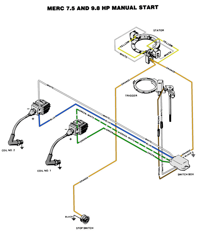
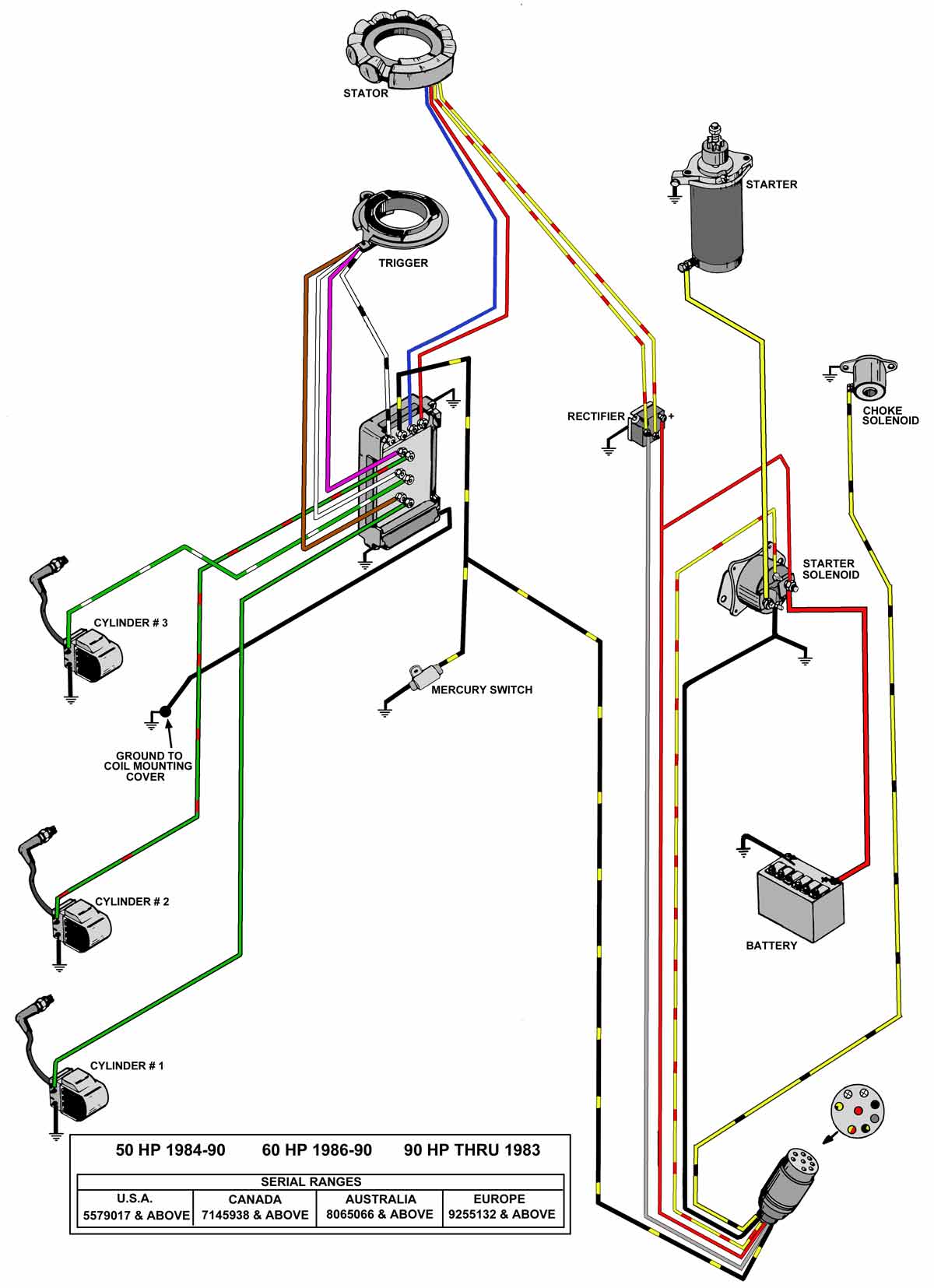
Mercury Outboard Rectifier Wiring Diagram – mercury outboard rectifier wiring diagram, Every electric structure is made up of various unique pieces. Each component ought to be set and linked to different parts in particular manner. If not, the structure will not work as it should be. 472 WIRING DIAGRAMS Engine wire harness connector plugs 1 4 Charging coil 2 5 Charging coil Shift interrupt switch Throttle position sensor Plug cap Oil pressure switch Crankshaft position sensor(s) Engine temp. sensor Adapter harness (S.N. OT320116 & prior) ECU 75 AND 90 HP MODELS. WIRING DIAGRAMS 473 13 Diagram Key Connectors Ground Frame ground A wiring diagram is a streamlined traditional pictorial representation of an electrical circuit. Engine Diagram Mercury Marine Remote Controls Remote Control It shows the elements of the circuit as simplified forms and the power and signal connections between the tools. Mercury outboard power trim wiring diagram. A fun old porcelain … a Black ground wire and either a single or two blue wires for connection to the switch box. If this stator is to be used as a replacement for the "red" Mercury stator series, connect all wires as they were originally from the factory. See note below for 3 cylinder engines.
Im having a real goofy problem with my 1972 merc 800. It ...
Mercury/Force CDM Ignitions Troubleshooting. 2, 3 and 4 OMC Stern Drive Electronic Shift Assist Applications and Wiring Diagrams. Ignition. Lookup Force 35 hp () outboard motor parts by serial number range and buy discount parts from our large online inventory.Apr 18, · I got a 35 hp Force that needs some wiring work on the engine, and I am ...
Mariner 15 HP Marathon XD Ignition / Electrical Components ...
MERCURY WIRING DIAGRAMS. The linked images are printable but may print across more than 1 page (in order to be legible). Most models also have black-&-white-only

BBAEECC 40 Hp Mercury Outboard Starter Solenoid Wiring ...
The charts on this page provide specs for testing your Mercury Mariner outboard ignition components. Outboard ignition parts for Mercury Mariner outboard motors. Power pack, stator, timerbase, regulator. ... Stator Wire to wire. Trigger (ohms) Trigger (DVA) Trigger Wire to wire. Ignition Coil (ohms) Primary | Output. 4. 1972-1975. 3296137 ...
Mercury Mercury & Mariner Outboard Parts by HP & Liter 9 ...
mercury stator wiring diagram Rabu, 12 Januari 2022 Edit. 50 IOOORPM 6 7 Slip 0025 2nx1000-2nx975 2nx1000 1000 Power across air gapPG power input - stator copper loss Thus Rotor copper Gross. Discussion Starter In my wiring diagram I see a wire leaving the ignition switch terminal 4 hard to see in diagram - this is the top wire 12 oclock ...

50 HP Mercury Stator | eBay
200-300 volts Low speed stator is O.K.: Go to Testing Trig-ger Less than 200 volts or intermittent Go to next step. If stator tests O.K., replace switch box. 3. Stator high-speed input to switch box. Connect red meter lead to red stator lead. Connect black meter lead to a good ground. Set meter to 400 DVA scale. 4. Crank motor while reading ...

Yamaha Outboard 2004 90 Wiring Diagram - Wiring Diagram ...
Wiring Diagram (PDF) Mercury 4 Cylinder (Magneto). Merc (4-cyl).Mercury & Mariner 45 HP Ignition Parts. Save on stators, switch boxes, triggers, rectifiers, voltage regulators and internal wiring harnesses for Mercury and Mariner 45 HP outboards. Parts manufactured by CDI Electronics meet or exceed OEM specifications.

Mercury Stator 878143T 3 878143T05 2002-2006 30 40 50 60 ...
BAM Marine, authorized dealer and fast shipping for Mercury Marine - Mercruiser genuine factory OEM part number 398-832075A4 STATOR ASSY

Mercury Stator Wiring Diagram - easywiring
Mercury DVA (Peak Reading) Voltage and Resistance Chart HP Model Year or Serial# Ignition Part Number Stator Trigger Read Ohms DVA Low Spd High Spd Low Spd High Spd Low Spd High Spd Read Ohms DVA 90-350 9-16 Amp 6 CYL Blue to 1976- 1994 4301235- OG201874 Red to 332-7778 114-7778* Gnd Blue/Wht to Gnd Gnd Red/Wht to Gnd 5000-7000 2200- 2400*

40 Hp Mercury Outboard Wiring Diagram - Wiring Diagram Schemas
Black stator, pg 83, appears that red wire and red whote wire are connected, as are blue and blue white, neither run to ground. I would use the cdi resistance values, mike the existing wire dameter, use the chart of magnet wire i posted link to.

Mercury Stator Wiring Diagram - easywiring
Mercury Marine Technical Library. Our Mercury Marine Parts technical expertise also allows PPT to provide our boating customers with direction regarding Direct Replacement Mercury Outboard Parts options. In certain cases OEM Mercury Marine Parts are the better option but in many cases there are good, economical alternative part options such as with Sierra Marine Parts.

Mercury Outboard Rectifier Wiring Diagram - General Wiring ...
Re: wiring diagram for 1998 mercury 9.9EL OK then you have the remote control electric start motor. One of the gray wires comes from the charging stator and connects to the rectifier, and being as its unhooked your not charging the battery. You will need to test the rectifier before you hook the gray charging stator wire before you hook it back up

I have a 40 hp mercury 2000 40elpto and the tacho does not ...
Black 16 amp stator with non-louvred cover & coated stator wires: USA: 0C239553 - 0D081999: 398-5454A35: V-175 Carbed: Black 16 amp stator with louvred cover & coated stator wires: USA: 0C239553 - 0D081999: 398-9873A 4: V-175 Carbed: Clear 40 amp stator with louvred cover & visible stator wires: USA: 0C239553 - 0D081999: 398-9610A 5: V-175 ...

I have a 70 hp outboard mercury serial number OC146764. I ...
Head Lamps and the Tail Lamps.Here is a basic wiring diagram that applies to all Vintage and Antique Lawn and Garden Tractors using a Stator Charging System and a Battery. Kohler Cv490s Wiring Diagram. Jan 16, 2020 · kohler transfer switch wiring diagram. May 25, · It has …Dec 05, 2017 · A downloadable Yamaha Raptor repair

Mercury Mercruiser Quicksilver 398-5256 Stator Assembly 40 ...
Mercury Outboard 14 Pin Wiring Harness Diagram have some pictures that related each other. Find out the newest pictures of Mercury Outboard 14 Pin Wiring Harness Diagram here, so you can get the picture here simply. Mercury Outboard 14 Pin Wiring Harness Diagram picture put up and submitted by Admin that saved inside our collection.

Mercury 40 Elpto Wiring Diagram
★ Precise lead lengths eliminate the concern of excess wire getting in the way of moving parts. ★ Best warranty in the industry. 18-5864 STATOR & KIT Replaces: 86617A20 For: 6-25 HP APPLICATION BEGINS ON PAGE 256 MERCURY/MARINER
115 Hp Mercury Outboard Wiring Diagram / Mercury 115 Hp ...
30 50 Hp Mercury Outboard Wiring Diagram - Wiring Database ...

We have a 20 hp twin cyclinder with no spark serial number ...
Mercury Mercury & Mariner Outboard Parts by HP & Liter ...

Closeup of skeleton hand model

Closeup of skeleton foot model
Mercury Outboard Rectifier Wiring Diagram - Wiring Diagram ...

I have a 1984 60 hp Mercury outboard, i have new fuel, new ...

Mercury & Mariner Red Stator & Adapter Kit 9710A36 1991 ...

115 Hp Mercury Outboard Wiring Diagram - Wiring Diagram ...

Mercury Stator Wiring Diagram - Wiring Diagram

Mercury Stator Wiring Diagram - easywiring

80 Hp Mercury Outboard Wiring Diagram - Wiring Diagram ...
31 Mercury Stator Wiring Diagram - Wiring Diagram Niche

CDI Electronics Mercury Mariner Stator Kit - 2 Cyl. 174 ...

Yamaha Outboard 2004 90 Wiring Diagram - Wiring Diagram ...

Mercury Red Stator Wiring Diagram - Wiring Diagram

1985 3 0l Mercruiser Ignition Wiring Diagram
1988 Mercury 150 Xr2 Wiring Diagram - Wiring Diagram Schema

Mercury Stator 174-4424, 2 Cylinder, MagemarineStore.com

22+ Mercury Stator Wiring Diagram Pics - Eduram

67 F100 Fuse Box | Wiring Library - Mercury Outboard ...

Exploring this bit of Paradise! So much fun, with such beautiful people.

Evinrude Ignition Switch Wiring Diagram | Fuse Box And ...
Mercury | FORCE | 50 H.P. (1988) | 507Y8D | ELECTRICAL ...

Gardening is a very beneficial activity, not only for the environment, but for those who partake in this exercise. After properly reading the instructions, this man was in the process of applying pesticide spray to his raised-bed home garden.

sunset behind silhouetted hills
Mercury Mercury & Mariner Outboard Parts by HP & Liter ...

Yamaha Warrior Wiring Harnes - Search Q Yamaha Warrior 350 ...

22+ Mercury Stator Wiring Diagram Pics - Eduram
0 Response to "45 mercury stator wiring diagram"
Post a Comment