44 request to exit wiring diagram
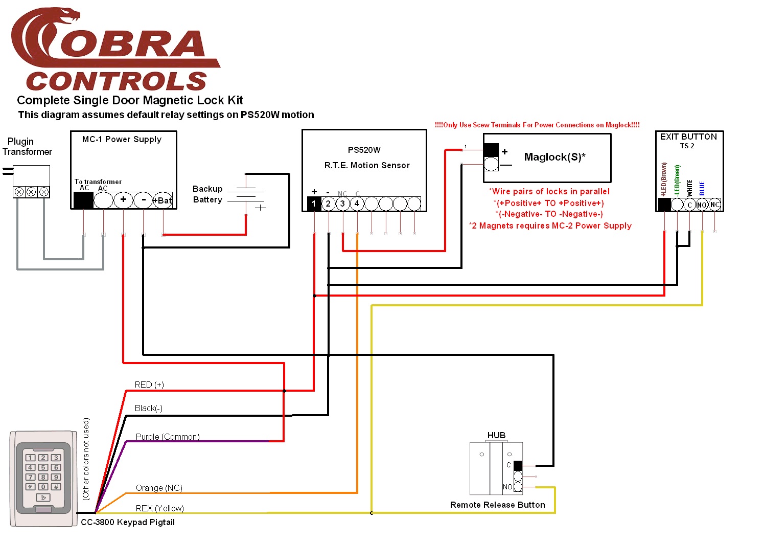
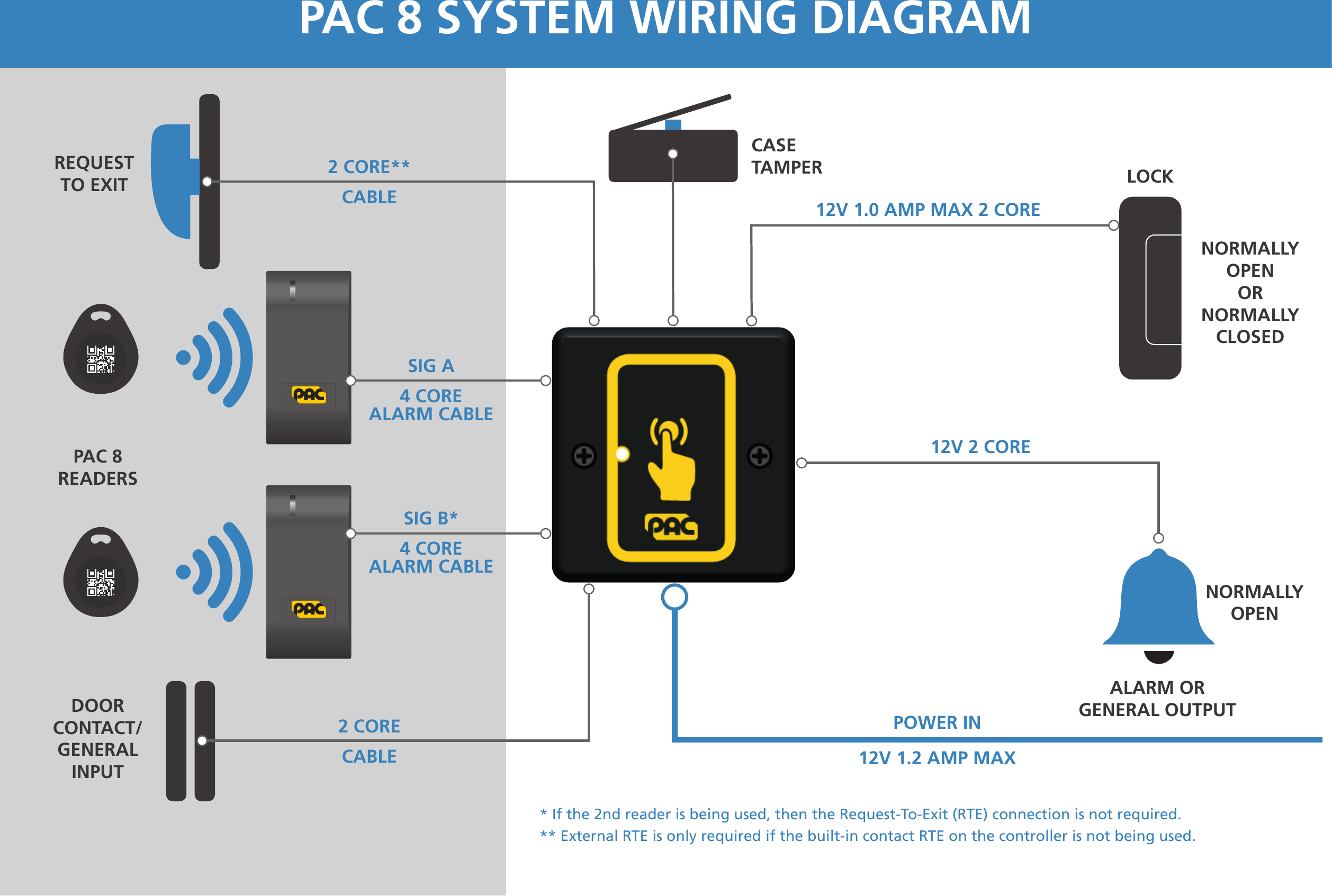
Option RX (Request to Exit), LX (Latchbolt Monitor), DPS (Door Position Sensor, available non-deadbolt models), DM (Deadbolt Monitor, available deadbolt models). See pricebook for additional lock options. Note: Messaging indicators are not available for the L909x Series L Series mortise indicators Function + cylinder Trim Finish Handing Option code Wiring. The basic hook-up consists of the REX (Request to Exit) device, a power supply, and a maglock. When the REX sees motion, power is removed from the maglock.
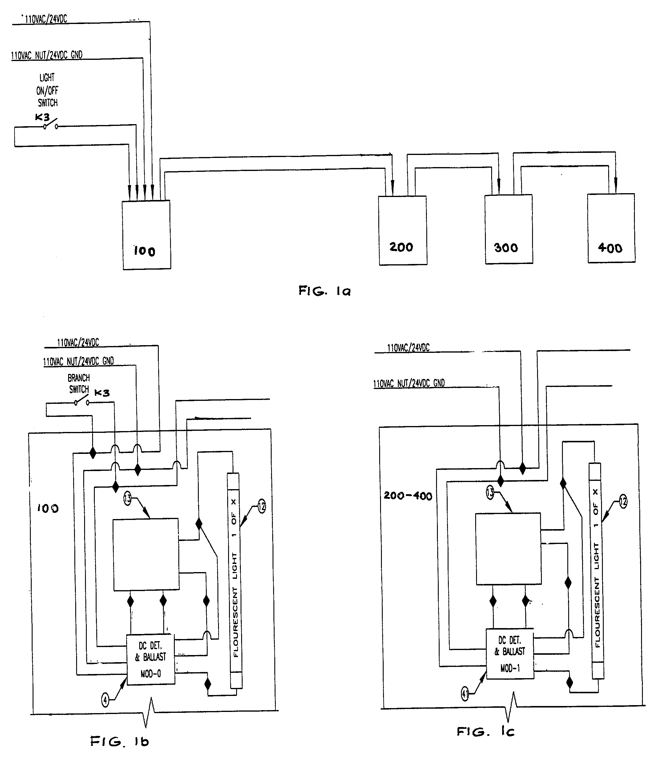
NOTE: Failure to spike protect the detector may result in shortening the life of the relay contacts. 3.6 Note location of detector features. Wire Terminals.8 pages
Request to exit wiring diagram
Wiring diagram The diagram below shows how to wire 8KW and 9KW electri˜ed locks. Figure 1—Wiring diagram for 8KW and 9KW electri˜ed locks (9KW with RQE shown) Run wires through the door or mount wires to the door sur-face with wire molding. To ˜nd the correct wire gauge for wire runs, see Figure 2 on the reverse side. RQE (Request-to-exit ... T.REX-LT-NL T.Rex request-to-exit detector with tamper and timer, white (unbranded) TREX-LT2 T.Rex request-to-exit detector with tamper, timer and 2 relays, white T.REX-LT2-NL T.Rex request-to-exit detector with tamper, timer and 2 relays, white (unbranded) T.REX-XL T.Rex request-to-exit detector with tamper, piezoelectric buzzer and timer, white A crucial step in setting up your push-to-exit button is properly wiring all the components. In an IP system like Kisi, this will involve the door lock, the access reader, the controller, the power supply, and the push-to-exit button (as well as optional contact sensors). The following diagram outlines the setup with an electric strike lock.
Request to exit wiring diagram. Request To Exit PIR sensors Installation Instructions 1.0 Description The DS160/161 is a passive-infrared (PIR) detector designed for request to exit (REX) interior applications. ... the wiring through the trim plate and into the base before mounting the base and trim plate onto a single gang electrical box. LocksOnline Wiring Diagram 004. Oct 30, · Request to Exit Wiring Diagram ds ds installation guide high performance request to 3 3 8 disabling the request to exit the ds can be disabled by using terminal r and an external device such as an access control or burglar alarm system. Push Buttons. ENFORCER Outdoor Piezoelectric Request to Exit Pushbutton -LARM U.S.A., Inc 3SECO Wiring the Manual Override: SD-6176-SSVQ and SD-6276-SSVQ Only Connect the manual override button with the included wires. Notes a. Remove the thin panel on the bottom of the plastic cover to allow wiring to pass through. b. Note: Before you begin wiring your doors, please see the recommended wires for the AC41. Connect the Lock (Access Power Controller - Dry Contact) When using an Access Power Controller (APC) which uses a dry contact, ensure that NONE is selected on the door power selection switch. The APC will detect if the AC41 relay is open or closed and translate that to the lock.
Wiring Diagram: Installation: 1. Run four wires through the wall to a single-gang or slimline back-box. 2. Connect the four wires from the back-box to the Request-to-Exit Sensor according the Wiring Diagram above. 3. Screw the plate into the back-box, taking care not to crimp the wires. 4. Remove clear protective film from the sensor before use. SECURITRON EEB2, EEB3N EXIT BUTTON WITH INTEGRATED TIMER INSTALLATION AND OPERATING INSTRUCTIONS DESCRIPTION Model EEB2 is a two-inch square, exit button, mounted on a stainless steel (S.S.), single gang key plate. Model EEB3N is a rectangular exit button, mounted on a 1 3/4" S.S. narrow stile key plate. Both EEB2 and EEB3N have a 3A switching Bosch associates work together with bosch request to exit wiring diagram, and comes equipped with a great way of electronic service has switches and ignition systems that. You at mount this universal garage door safety sensor to the existing wiring. APP on your phone or a, you can remotely control and air conditioner from tag in the. RCR-REX Request-to-Exit Dual Technology Motion Sensor Installation Instructions 2 Wiring This section provides examples of different wiring options. The options are all shown in the fail safe mode. Basic hook-up Figure 4 shows the basic hook-up for the RCR-REX, a power supply and a magnetic lock. When the sensor sees motion, power
The following common wiring diagrams are available: One Single Door with Panic Bar. Electric Latch Retraction, with Auto Operator ... riser diagrams falcon exit devices ... wiring diagram request form . Common Wiring diagrams . wiring diagram for QEL panics ... THIS WIRE DIAGRAM, BE SURE ALL PRODUCTS ARE VOLTAGE COMPATIBLE. ... Activating the Request-to-Exit (REX) motion sensor will unlock the magnetic lock ...1 page - WIRING INSTRUCTIONS— Magnetic lock or fail safe strike with button, keypad, maintained button and remote receiver. wired in series Power Supply for fail safe strikes and magnetic locks should be DC. If this is not available you may use an AC power source and wire inline a "Full Wave Bridge" rectifier. This will conver t the AC to DC. 915Mhz. Wireless Door Control System. 2" Sq. LED Illuminated Exit Switch, w/ timer. Camden's CM-RQE70 PIR 'REQUEST TO EXIT' Detectors provide the latest word in design, with a complete list of "high performance" features, including secondary activation device input, door monitoring, two relay outputs, and tamper alarm.
Request To Exit Wiring Diagram - Complete Wiring Schemas
system should have a two-terminal REX (request to exit) input. When this input is closed, the access system will operate its lock control relay to release the lock and will not create an alarm signal as it will consider the exit event a "legal" one. Wiring is shown in Figure 5. Note that with

mountain covered with snow under white clouds
RCR-REX Request-to-Exit Dual Technology Motion Sensor Installation Guide Introduction ... Route wiring to the sensor mounting location. If you are using the wall plate, pull the wires through the cable entry hole (Figure 3). Figure 3: Mounting and wiring access 4. Insert the mounting screws into the back (wall mount) or

Dc12v Infrared Sensor Access Control Door Exit Button ...
Instructions for wiring a VP1 reader-controller with a Request-to-Exit device. Instructions for wiring a VP1 reader-controller with a Request-to-Exit device.

2018 Diy 125khz Rfid Black Controller Access Control Kit ...
56- Electric Latch Retraction Exit Devices Installation and Wiring Instructions With Optional 53- Latchbolt; 55- Request to Exit; and TL- (SARGuide) Connection Instructions FOR INSTALLATION ASSISTANCE CONTACT SARGENT • 1-800-810-WIRE (9473) • www.sargentlock.com SECTION I: OVERVIEW 1. Description

Push To Exit Button Wiring Diagram - Drivenheisenberg
About Press Copyright Contact us Creators Advertise Developers Terms Privacy Policy & Safety How YouTube works Test new features Press Copyright Contact us Creators ...
35 Push To Exit Button Wiring Diagram - Wiring Diagram ...
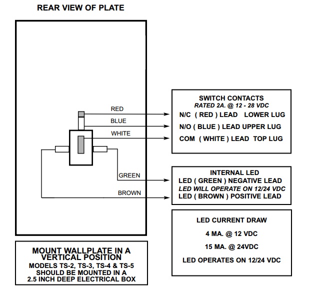
The TS-2 request to exit station, with square push button, provides a convenient way to add authorized access control to a variety of applications. Features. Standard Features. Switch mounted on single gang wall plate with 430 stainless steel finish;
35 Push To Exit Button Wiring Diagram - Wiring Diagram ...
The L-Series switched to a handed modular three-wire request to exit (RX) switch.This change was originally completed on electrified locks in October 2014. The RX switch will have a molex connector attached re quiring use of Allegion Connect Harnesses and IVES hinges, or connector can be snipped off and traditional splicing methods employed to wire lock.

Wiring Diagram Of Providing Power To A Fail Safe Maglock ...
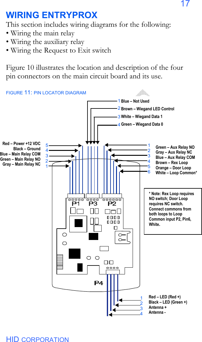
The button to request exit wiring diagram can accommodate. Wire connectors packages show the minimum and maximum wires and sizes allowed. Alarm output and character separate voltage free relay. The HID Access Manager login dialogue will launch. TODO: we urge review the class names and whatnot in up here.
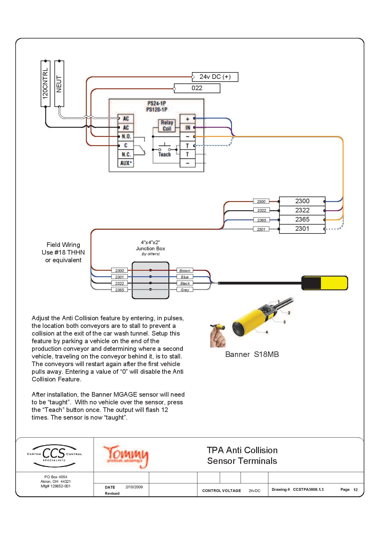
Anti Collision Wiring Diagram - Tommy Car Wash Systems
DS150i/DS151i Installation Guide Request-to-Exit PIR Detectors 1.0 Description The DS150i is a passive-infrared detector designed for request to exit (REX) applications. It is UL Listed as an access control device under the UL 294 standard and is listed for Class I for UL Canada (ULC-S319). For

Emergency Test Switch Installation - Ektor UK
Wiring Diagram: Installation: 1. Run four wires through the wall to a single-gang or slimline back-box. 2 ...4 pages
20 New Request To Exit Wiring Diagram
The single gang TS-7 and narrow stile TS-9 request to exit stations, with rectangular push button, provide a convenient way to add authorized access control for a variety of applications. TS-7 and TS-9 are available with timer relay for applications that require door to remain unlocked for a specified time.
.jpg)
Push To Exit Button Wiring Diagram - General Wiring Diagram
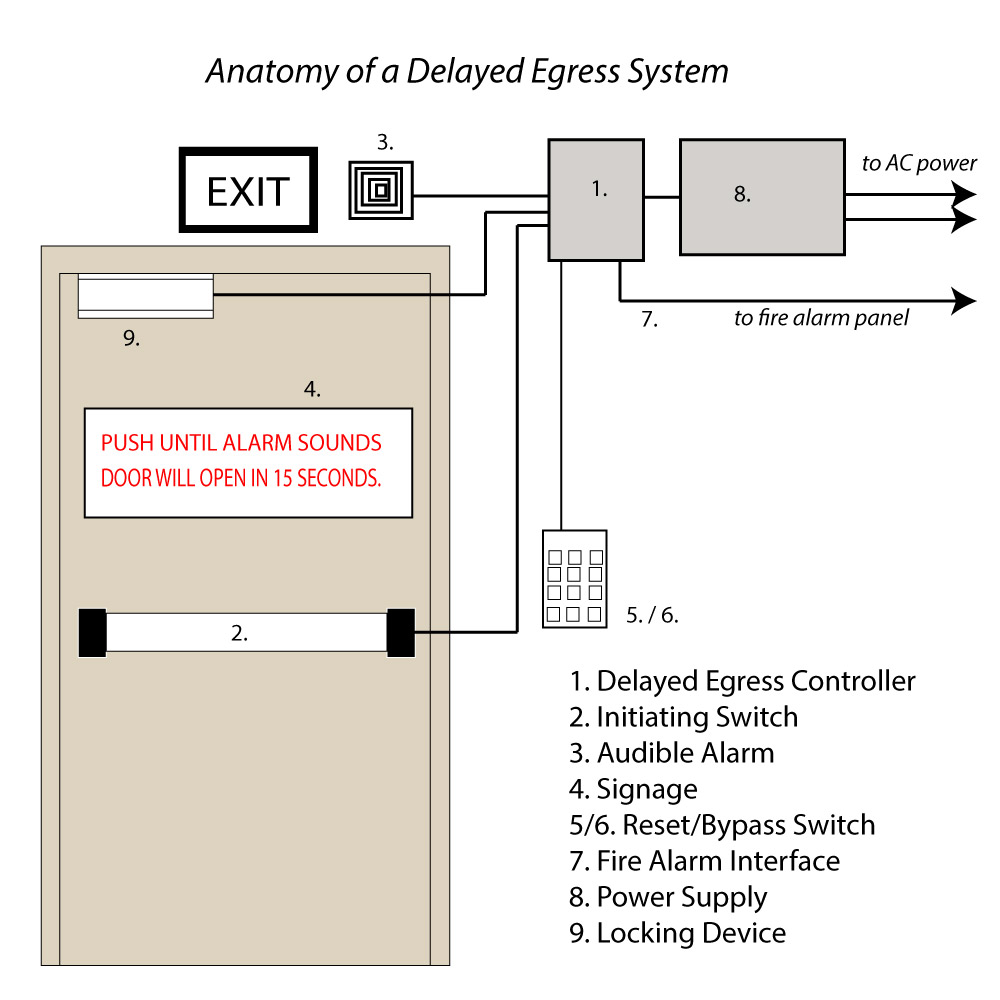
BEA has a complete line of request-to-exit (REX) products including sensors, locking devices, push buttons and keypads. Building codes often require two forms of exit devices on a door, such as a motion sensor and a push button, to ensure that occupants are safely able to exit a building. Our sensors help meet these codes.
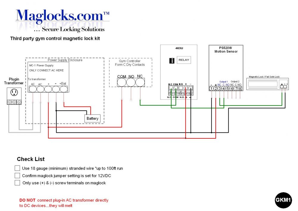
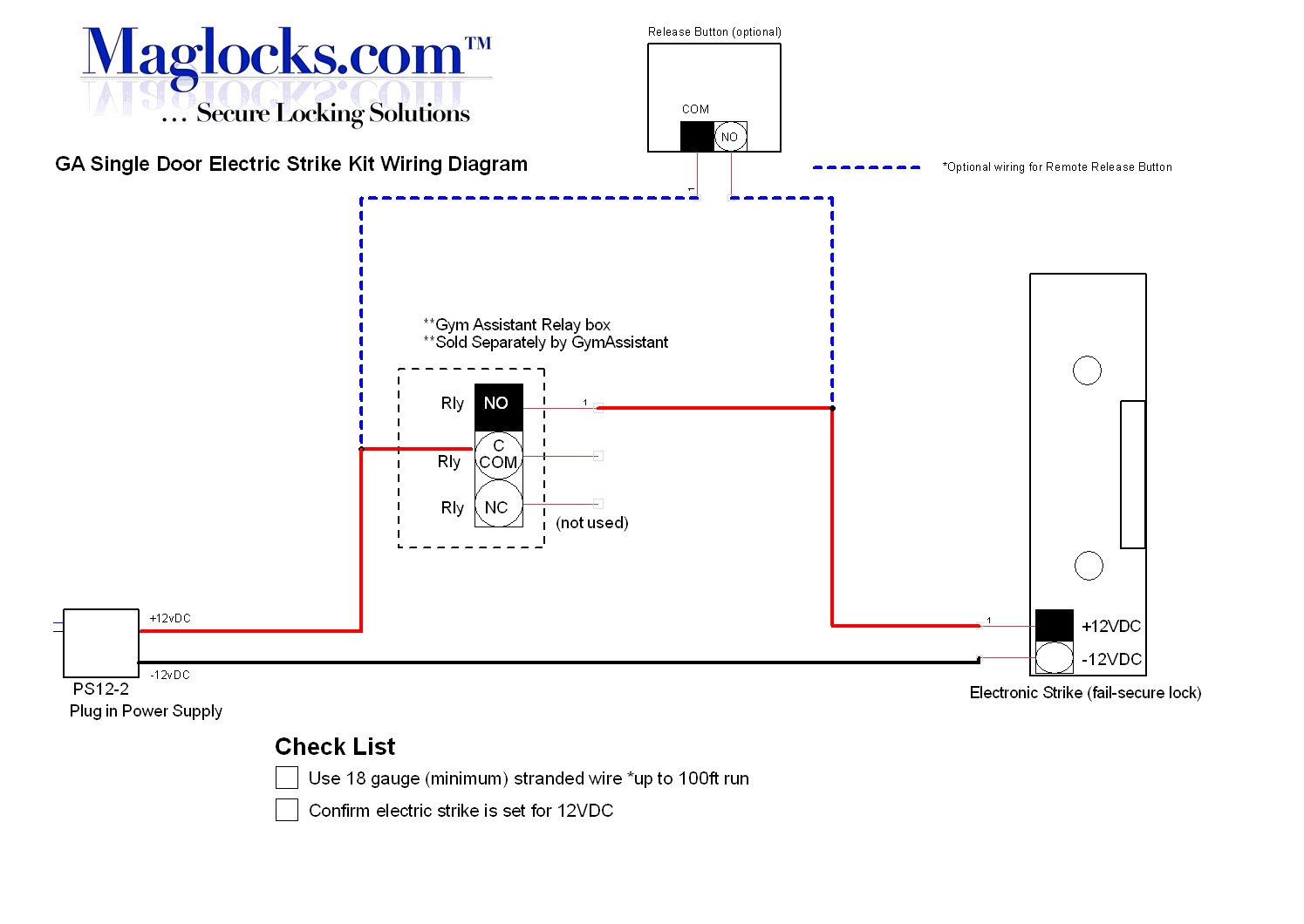
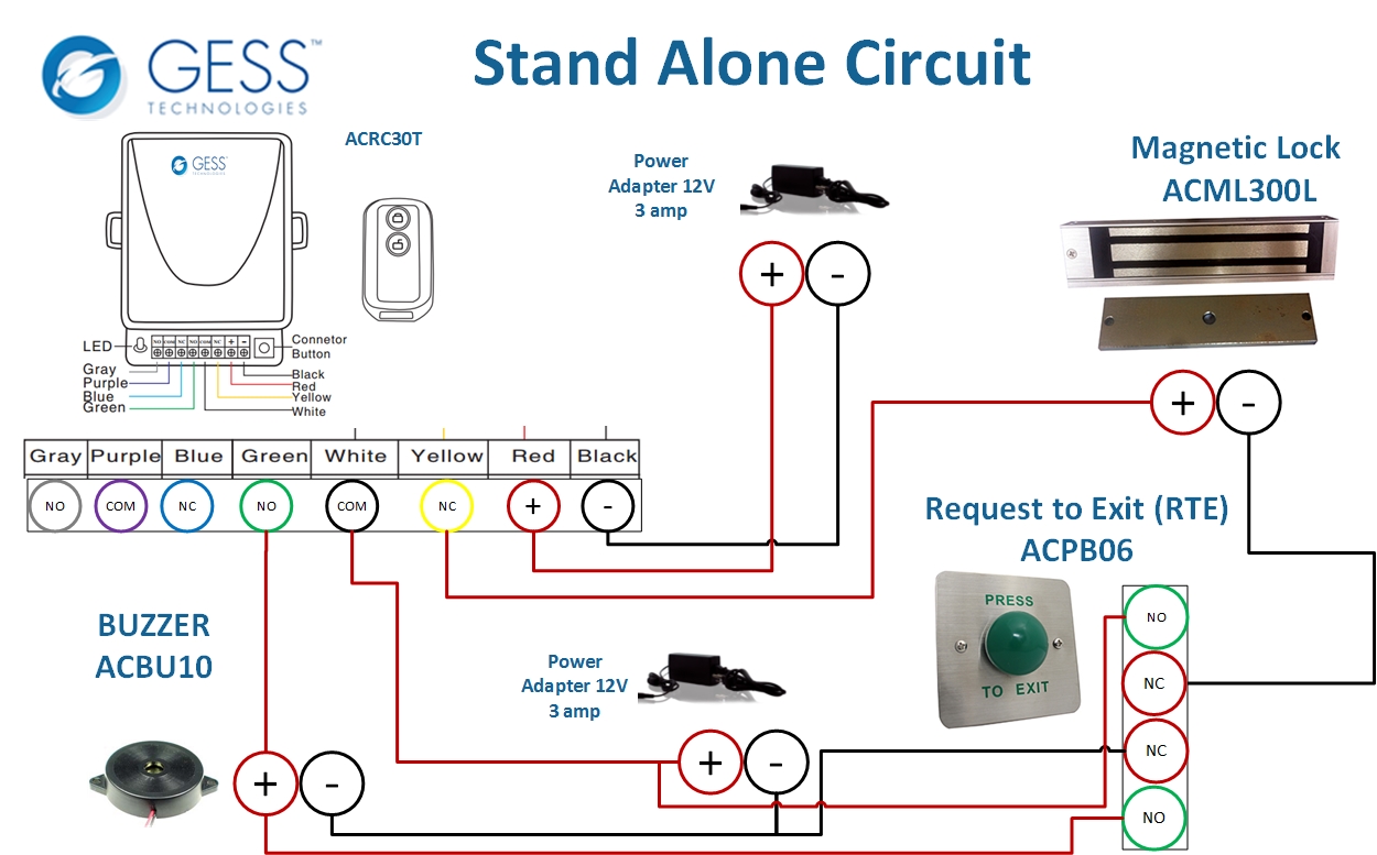
Gym Assistant, Door Magnetic Lock Kit for Storefronts ...
How to connect a Request to Exit button in a Kisi stand-alone setup. When installing Kisi as a stand alone product on a Fail-Safe lock, it is important to understand how to wire necessary, non-Kisi components to the setup. This guide specifically will explain the wiring of a Request to Exit (REX) button.

Push To Exit Button Wiring Diagram - Wiring Diagram
Request To Exit PIR sensors Installation Instructions 1.0 Description The DS160 is a Passive Infrared Detector (PIR) which is UL Listed as an Access Control Device under the UL 294 Standard. It is designed for "Request To Exit" (REX) interior applications.

Resources | Yale - Locks, Access Control & Door Hardware ...
A crucial step in setting up your push-to-exit button is properly wiring all the components. In an IP system like Kisi, this will involve the door lock, the access reader, the controller, the power supply, and the push-to-exit button (as well as optional contact sensors). The following diagram outlines the setup with an electric strike lock.

unknown
T.REX-LT-NL T.Rex request-to-exit detector with tamper and timer, white (unbranded) TREX-LT2 T.Rex request-to-exit detector with tamper, timer and 2 relays, white T.REX-LT2-NL T.Rex request-to-exit detector with tamper, timer and 2 relays, white (unbranded) T.REX-XL T.Rex request-to-exit detector with tamper, piezoelectric buzzer and timer, white

Push To Exit Button Wiring Diagram - Free Wiring Diagram
Wiring diagram The diagram below shows how to wire 8KW and 9KW electri˜ed locks. Figure 1—Wiring diagram for 8KW and 9KW electri˜ed locks (9KW with RQE shown) Run wires through the door or mount wires to the door sur-face with wire molding. To ˜nd the correct wire gauge for wire runs, see Figure 2 on the reverse side. RQE (Request-to-exit ...
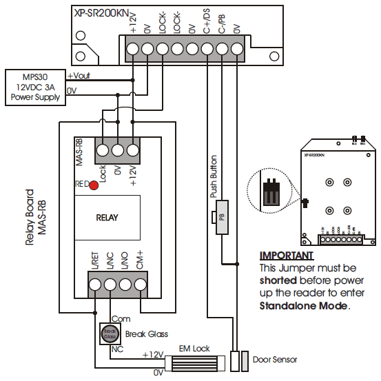
Wiring connection diagram for XP-SR200K | MicroEngine ...

person holding red metal frame

Heath Zenith Motion Sensor Light Wiring Diagram - Wiring ...

Double Door Laundromat Magnetic Lock Kit Keypad

How to Install a Push-to-Exit Button

blue and white exit signage mounted on brown brick wall
Hone Your Access Control Knowledge
Request To Exit Wiring Diagram - Complete Wiring Schemas

Wiring Diagrams - Cosine Developments

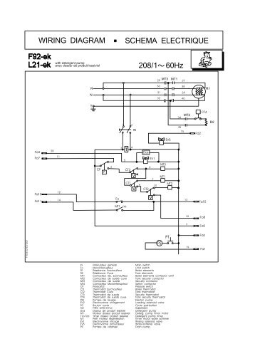
WIRING DIAGRAM - ekey ?· WIRING DIAGRAM WIRING DIAGRAM FOR ...

Access Control Cables and Wiring Diagram | Kisi
Rmr-16 Emergency Light Wiring Diagram
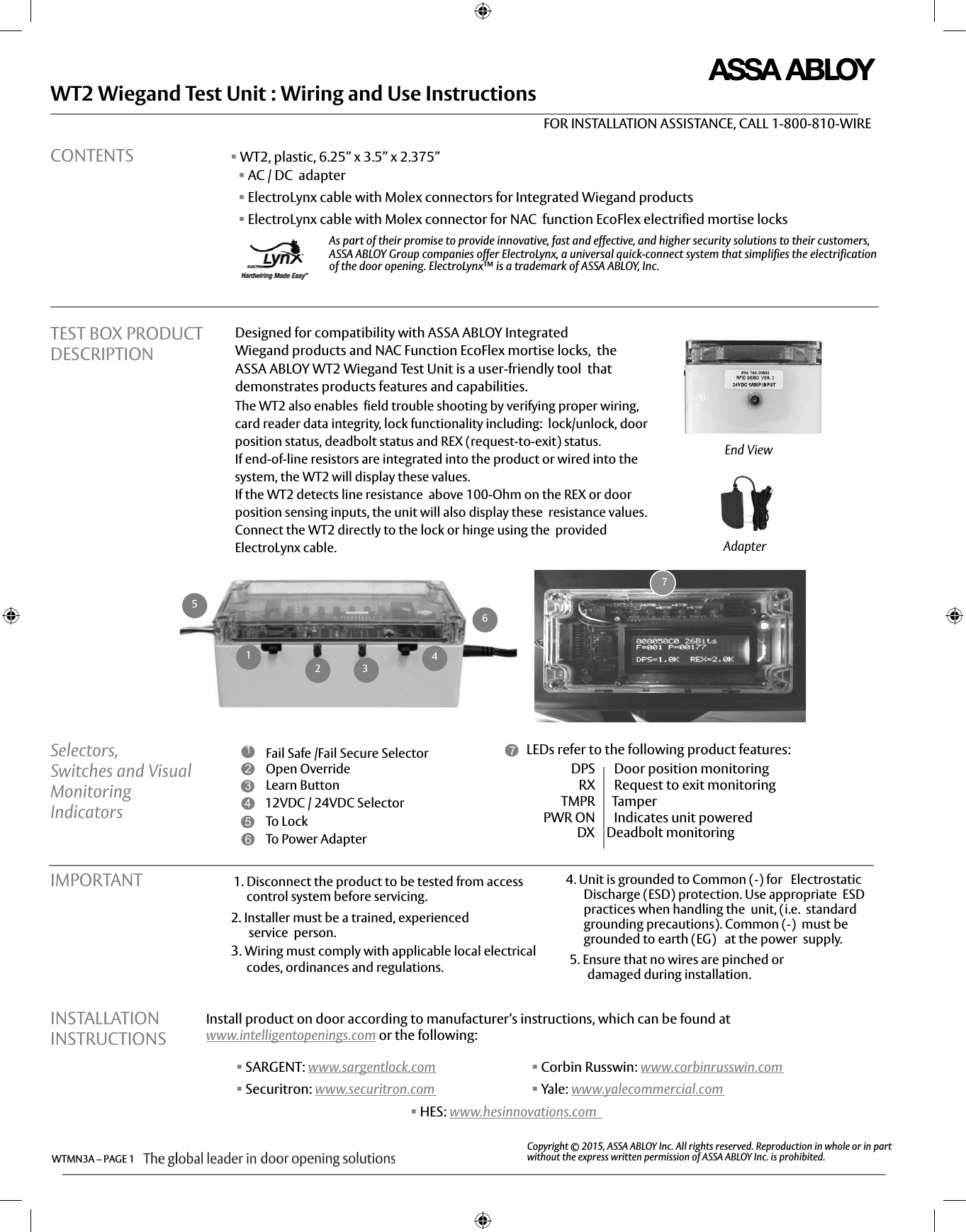
Securitron WT2 Wiring And Use Instructions WTMN3A I 500 24060

Push To Exit Button Wiring Diagram - Hanenhuusholli
Push To Exit Button Wiring Diagram - Free Diagram For Student
Enforcer Push To Exit Wiring Diagram
Achieving a Smart Access Design
32 Request To Exit Wiring Diagram - Free Wiring Diagram Source

Push To Exit Button Wiring Diagram - Free Wiring Diagram
Securitron Exit Button Wiring Diagram
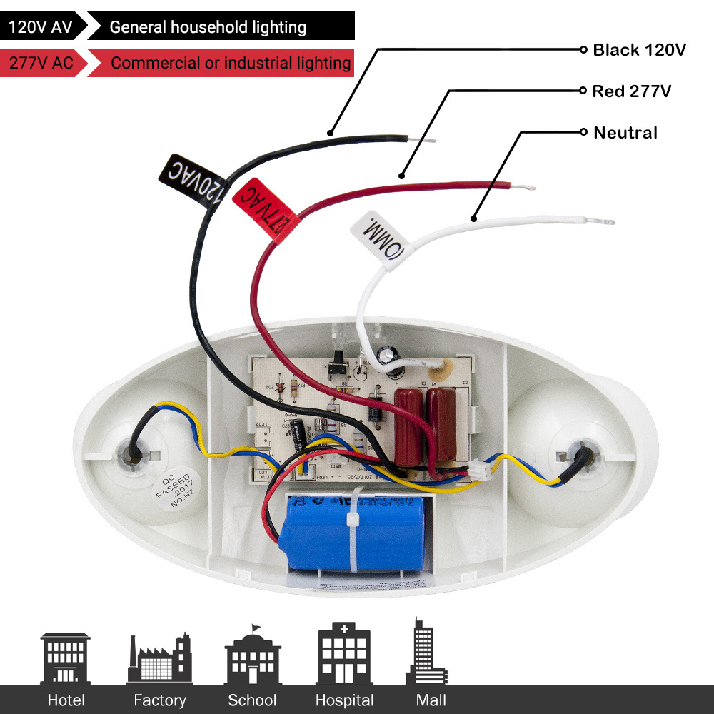
Exit Sign Wiring Diagram 120v 277v - Wiring Diagram & Schemas

unknown
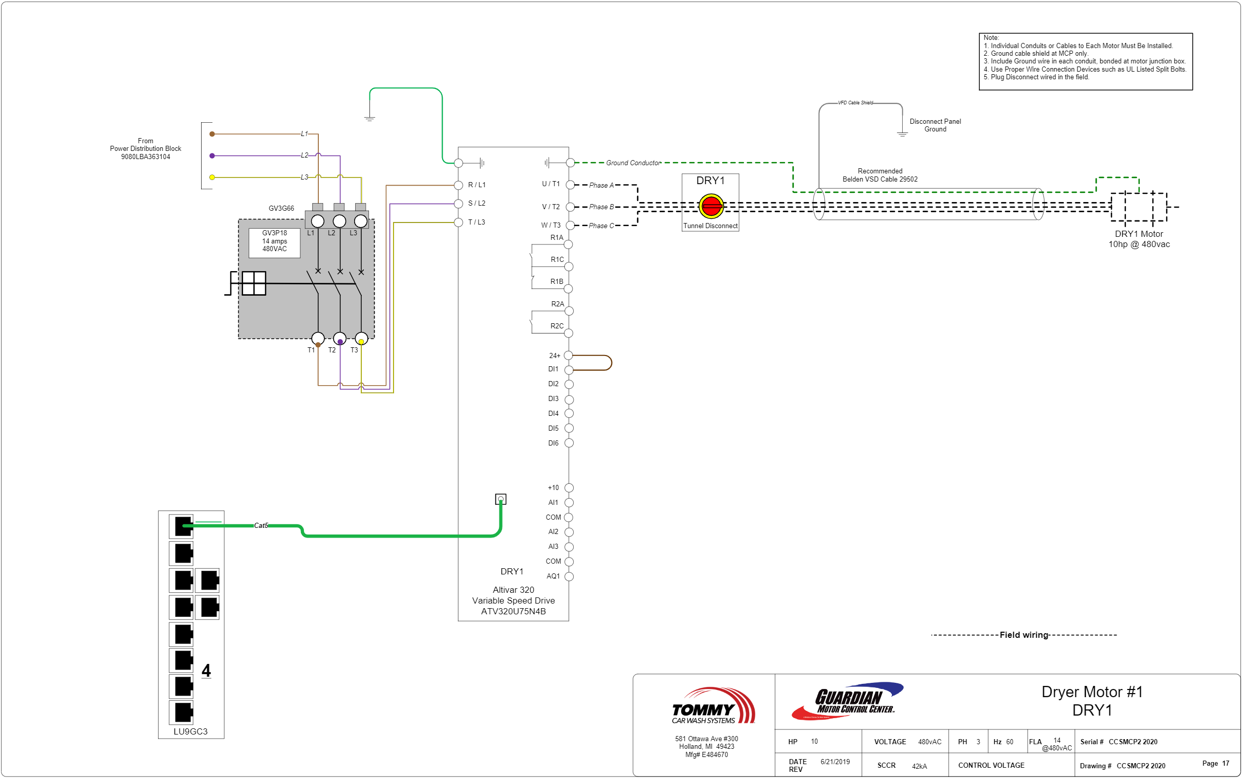
Blower Wiring Diagram (With VFD) - Tommy Car Wash Systems

2 person in red jacket and black pants riding on snow ski

Request To Exit Wiring Diagram - General Wiring Diagram
Request To Exit Wiring Diagram - Complete Wiring Schemas

unknown
0 Response to "44 request to exit wiring diagram"
Post a Comment