44 3 to 1 pulley system diagram
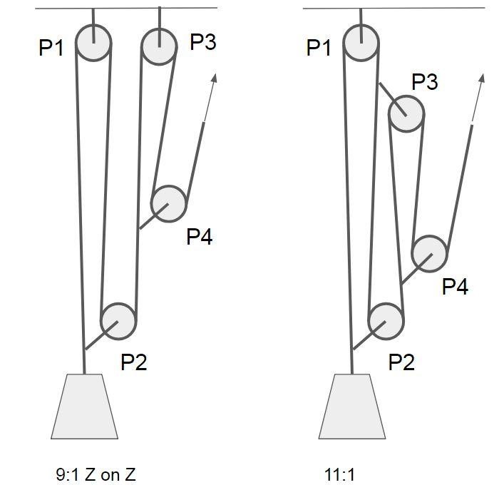
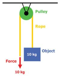
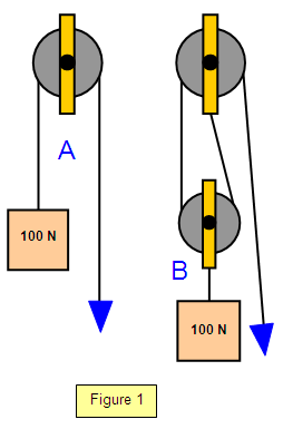
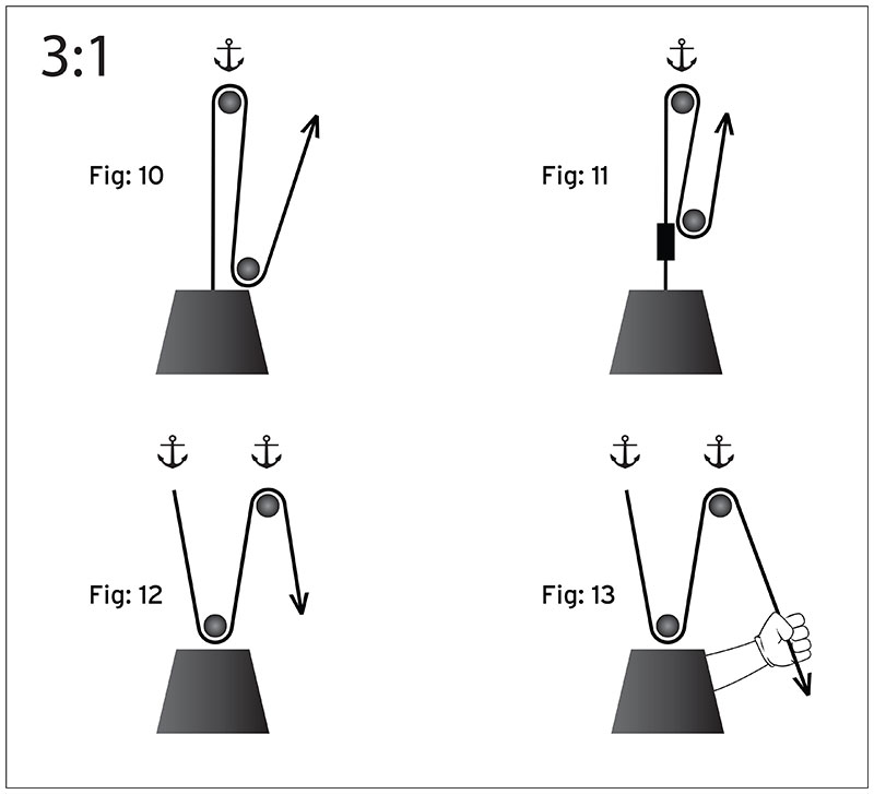
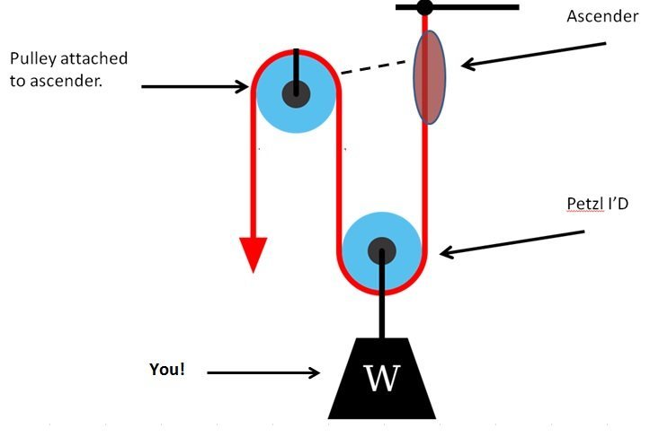
Diagram 3 shows three rope parts supporting the load W, which means the tension in the rope is W/3. Thus, the mechanical advantage is three-to-one. By adding a pulley to the fixed block of a gun tackle the direction of the pulling force is reversed though the mechanical advantage remains the same, Diagram 3a. This is an example of the Luff tackle. Note: the advantage of a 3:1 system is its ease of setup and that it can easily be converted to a complex system (7:1) with one additional pulley and some cord.
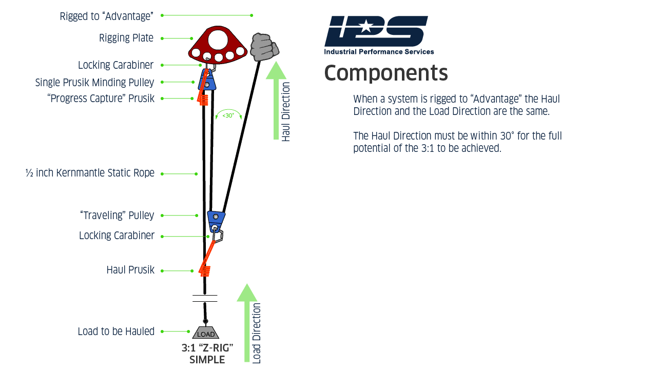
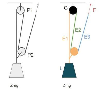
Aug 30, 2017 ... A few simple pulley systems are most frequently used. The most common is a 3:1 mechanical advantage, sometimes called a “Z” rig because when ...

3 to 1 pulley system diagram
The Speed Ratio is the ratio of angular velocity of the input pulley of a system to the angular velocity of the output pulley. If you've calculated gear ratios, it is almost exactly the same! This is all based on a pulley's reference diameter, as defined below: Reference/Pitch Diameter: The working diameter of the pulley, where the belt or cable contacts the pulley. #1 The "block" assembly is poorly thought out. It alone accounts for 3" of wasted space. Eliminate it. Remove the pulley assemblies and attach them directly to the ceiling or to a small piece of wood. I used some 3"x1" wood scraps that I had laying around. 1. Best in Customer Support . We pride ourselves in our customer support. We do everything we can to provide you with complete answers to any questions you might have, from orders to technical support. 2. Fast Shipping . If ordered by 1:00 pm PST, Monday through Friday, we ship all in-stock that afternoon. 3. Easy Returns
3 to 1 pulley system diagram. Jan 21, 2018 ... The 3:1 Z-Rig is one of the quintessential mechanical advantage system used by rescuers. This system when offset requires 1/3 of the rope ... 2. A cargo lift system that allows for items to be hoisted to higher floors is a pulley system. 3. Wells use the pulley system to hoist the bucket out of the well. 4. Many types of exercise equipment use pulleys in order to function. Diagram 3 shows that now three rope parts support the load W which means the tension in the rope is W/3. Thus, the mechanical advantage is three. By adding a pulley to the fixed block of a gun tackle the direction of the pulling force is reversed though the mechanical advantage remains the same, Diagram 3a. This is an example of the Luff tackle. Jan 16, 2022 · 1) The side mass falls a small distance vertically under gravity. 2) it pulls the top mass a small distance to the right. 3) An internal force at the pulley moves the large block a very small distance to the left. Note that the CoM (horizontal component) of the system has not changed and a gap has opened up between the large block and the side ...
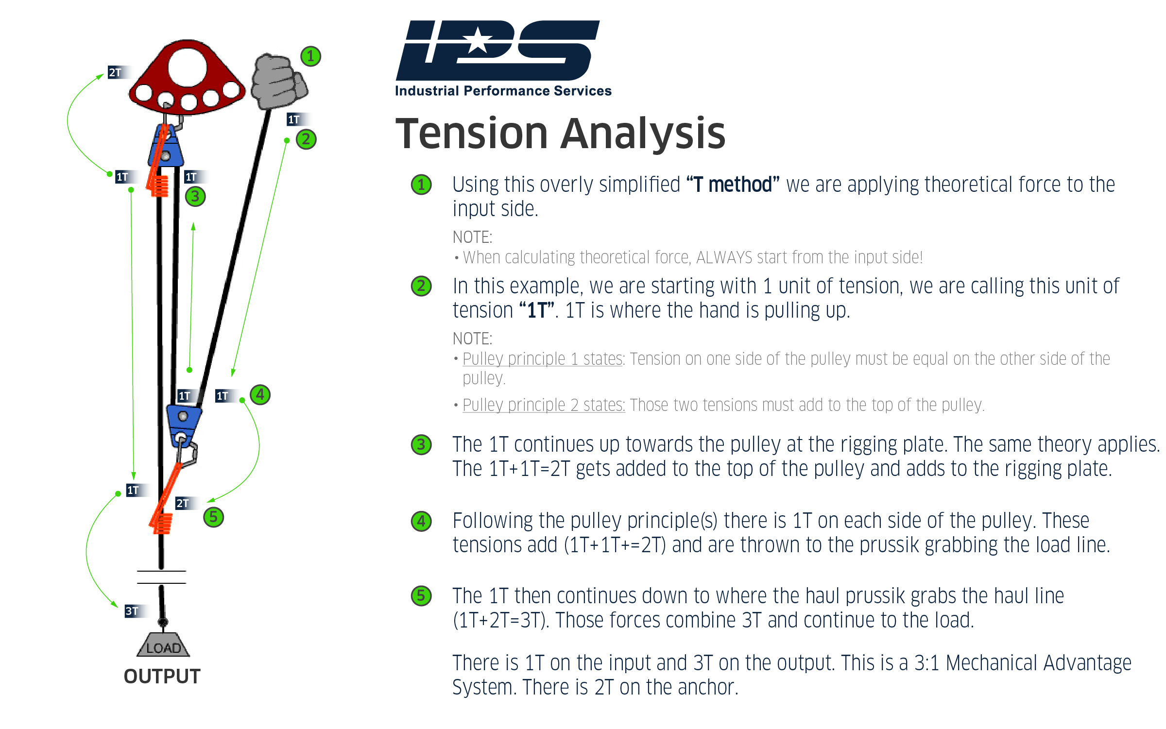
This video demonstrates how to build a “theoretical” 3:1. I do not take into account the factors of friction and pulley efficiency. Feb 3, 2019 ... There are three strands of rope going to and from the load and load strand, so this means it's a 3:1 MA. This is also known as a “Z drag”, ... 1) 4 newtons 127 degrees. 2) 3 newtons 37 degrees. 3) 2 newtons 290 degrees. 4) 6 newtons 190 degrees Pulley systems are used to provide us with a mechanical advantage, where the amount of input effort is multiplied to exert greater forces on a load. They are typically used for hauling and lifting loads but can also be used to apply tension within a system such as in a Tensioned Line or Tyrolean.
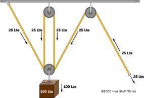
Jul 30, 2017 - Whoa, you've rolled right in to the Pulley Systems section! Keep the wheels turning… Apr 2, 2017 ... You can verify that it is a 3 to 1 by counting the legs of rope acting on the moving pulley. The first 2 are obvious – from stickman to pulley ... Rigging a 3:1 System. Some rescuers find it challenging to remember how to rig a 3:1 system. The following process may make it easier to remember: First rig a 1:1 system. The rope comes from the load and goes through one pulley. Easy enough. Now add "capture" Prusiks that will hold the load if you let go of the rope. Jul 5, 2021 - Explore Bob DeFoor's board "Pulley systems", followed by 170 people on Pinterest. See more ideas about pulley, block and tackle, pully system.
Does an MA system put more load on the anchor? — Alpine Savvy
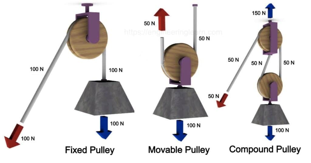
3 Types of Pulleys. A pulley is one of six classic "simple machines" used to change the direction or magnatude of the force required to do physical work ...
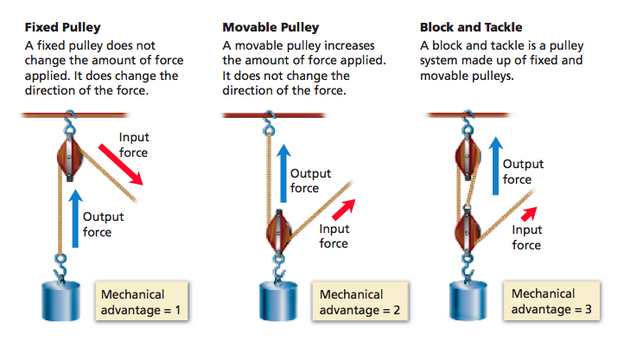
Types of Pulleys and How do They Work? - Pulleys
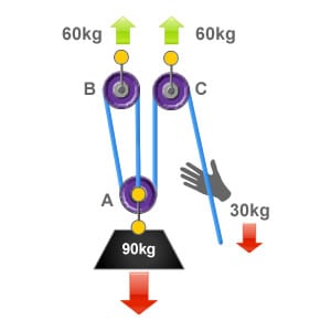
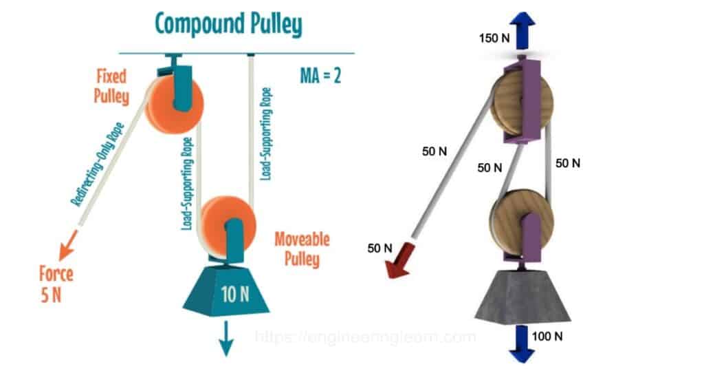
Jul 31, 2019 · This forms the 3:1 mechanical advantage, finally the rope is redirected by pulley C back down to the user who applies an effort of 30kg to raise the 90kg load. An easy way to calculate the ratio of a pulley system is to count the amount of lines that apply effort on the load. In this system there are three ropes that exert effort on to a load of 90kg, so each rope is supporting 1/3 of the loads weight (30kg).

DNA pulley system. ( A ) Schematic of the experiment. The ...
A pulley system has a velocity ratio 3. Draw a diagram showing the point of application and direction of load (L), effort (E) and tension (T). If lifts a load of 150 N by an effort of 60 N. Calculate its mechanical advantage. Is the pulley system ideal? Give reason.
The 3:1 Pulley System - ropebook
1. Best in Customer Support . We pride ourselves in our customer support. We do everything we can to provide you with complete answers to any questions you might have, from orders to technical support. 2. Fast Shipping . If ordered by 1:00 pm PST, Monday through Friday, we ship all in-stock that afternoon. 3. Easy Returns
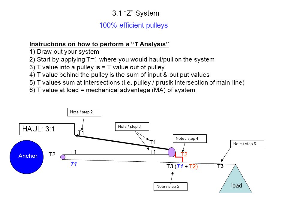
3:1 “Z†System 100% efficient pulleys Instructions on how to ...
#1 The "block" assembly is poorly thought out. It alone accounts for 3" of wasted space. Eliminate it. Remove the pulley assemblies and attach them directly to the ceiling or to a small piece of wood. I used some 3"x1" wood scraps that I had laying around.
Pulley system analysis | RopeLab Online
The Speed Ratio is the ratio of angular velocity of the input pulley of a system to the angular velocity of the output pulley. If you've calculated gear ratios, it is almost exactly the same! This is all based on a pulley's reference diameter, as defined below: Reference/Pitch Diameter: The working diameter of the pulley, where the belt or cable contacts the pulley.

Block and Tackle Pulley System | Options and Modeling ...

Pulley System Question : r/Mcat
Alpine Recreation - Trek | Climb | Ski
Powerful Pulleys - Lesson - TeachEngineering
Z-Rig Construction – Safety, Rescue, Training, Catalyst and ...
How to calculate mechanical advantage - Petzl USA
Pulley system analysis | RopeLab Online
How to calculate mechanical advantage - Petzl USA

Overview of a simple pulley system — Alpine Savvy
Z-Rig Construction – Safety, Rescue, Training, Catalyst and ...
schoolphysics ::Welcome::

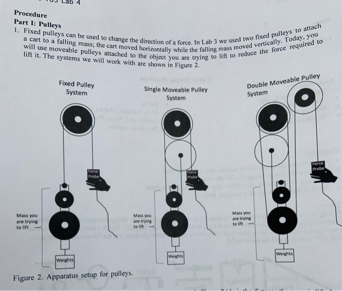
Pulleys

Schematic of a belt-pulley and gear-pair transmission system ...
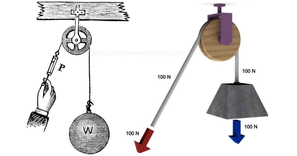
How a Block and Tackle Works | HowStuffWorks
Types of Pulley: Definition, Uses, Diagram, Examples ...

Robotic MECHANISMS - PULLEY SYSTEMS 51005 - Robotpark ACADEMY ...

Mechanical Advantage for Pulley Systems | Mechanical ...
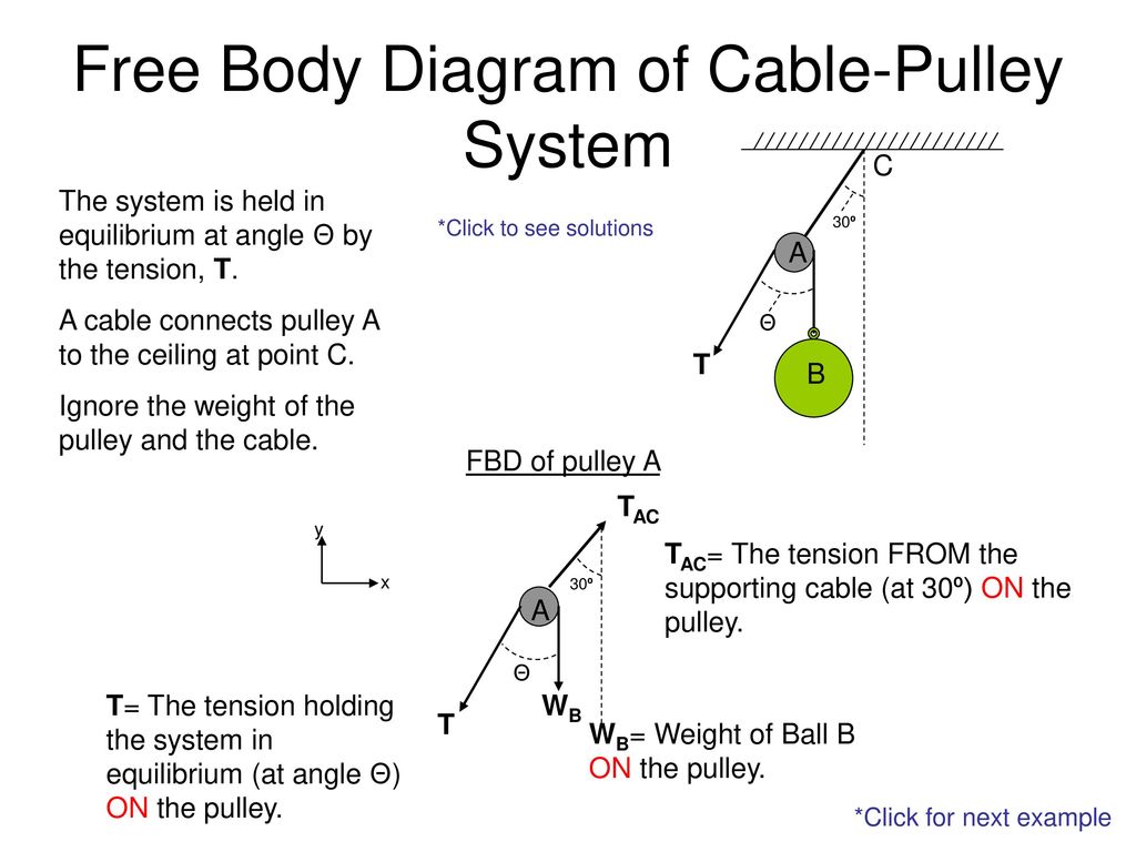
Free Body Diagram of Cable-Pulley System - ppt download

The Problem with Pulleys | Carolina.com
Types of Pulley: Definition, Uses, Diagram, Examples ...

Pulley system-Types|Mechanisim|Application - DewWool
Solved 2. (3 pts) Draw a free-body diagram for the force ...

Mechanical Advantage Explained | Educated Climber.com

Jacobs Physics: Three masses connected over a pulley
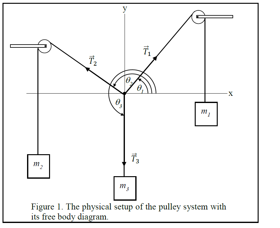
Solved 2 3 Figure 1. The physical setup of the pulley system ...
Pulleys and Lifting - Question 1

Pulleys – Simple Machines for Kids – Inventors of Tomorrow
Mechanical Advantage Systems 1
Types of Pulley: Definition, Uses, Diagram, Examples ...

Simple machines
Pulley system analysis | RopeLab Online
DMM Professional - Resistance is futile

A Single Movable Pulley and Mechanical Advantage | Science ...
Ascending with I'D

Pulley Systems - Flaschenzug | Pulley, Math about me ...
Mechanical Advantage Systems 1
How to calculate mechanical advantage - Petzl USA

Mechanical Advantage Explained | Educated Climber.com
0 Response to "44 3 to 1 pulley system diagram"
Post a Comment