41 msd 3 step wiring diagram
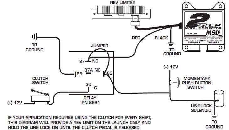
As an example, we'll use a drag car with a Three Step Module Selector plugged into the rpm socket of a 7AL-2 Ignition. The different rpm modules are activated when 12 volts are applied to a corresponding wire. By connecting one wire to the line-lock circuit, one module will be activated during the burnout. This helps keep tire temperatures consistent. When the line-lock button is released ... MSD 2 Step Clutch Wiring Diagram. Jump to Latest Follow 1 - 15 of 15 Posts. D. DougA · Premium Member. Joined Jul 14, 2002 · 4,538 Posts . Discussion Starter · #1 · Feb 23, 2010. Only show this user ...
Msd 3 Step Wiring Diagram from i2.wp.com To properly read a wiring diagram, one has to find out how typically the components in the program operate. For example , if a module will be powered up also it sends out a new signal of 50 percent the voltage plus the technician will not know this, he'd think he offers a problem, as this individual ...

Msd 3 step wiring diagram
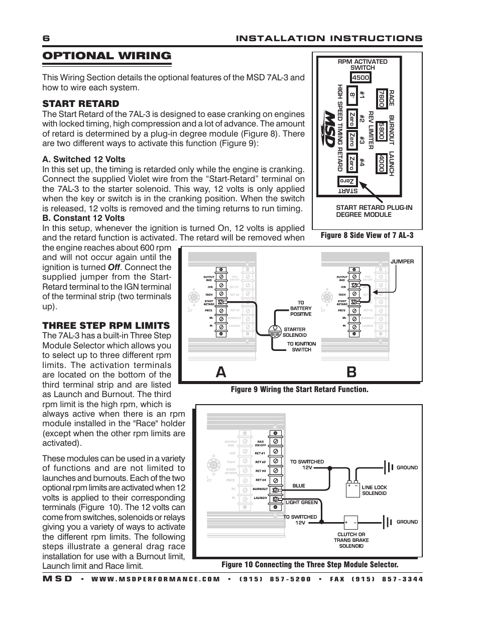
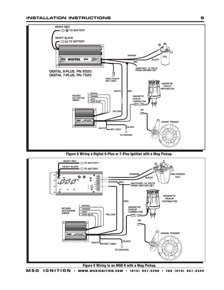
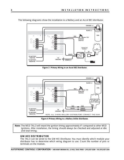
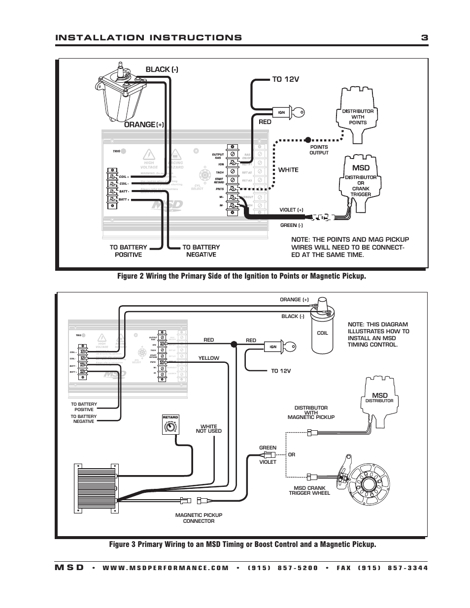
Note: The MSD 7AL-3 will retard the ignition timing approximately 4° compared to other MSD Ignitions. Read online or download PDF • Page 9 / 12 • MSD 7AL-3 Ignition Control Installation User Manual • MSD For the car. Choose the appropriate wiring diagram from the reverse side and wire as shown. INSTALLATION INSTRUCTIONS 3 AUTOTRONIC CONTROLS CORPORATION • 1490 HENRY BRENNAN DR., EL PASO, TEXAS 79936 • (915) 857-5200 • FAX (915) 857-3344 Figure 4 Wiring an MSD 6 Series Ignition with a Mag Pickup. Figure 5 Wiring an MSD 7 Series Ignition with Points/Amplifier. Mar 07, 2019 · msd 3 step wiring diagram wiring diagram datasource. Architectural wiring diagrams play in the approximate locations and interconnections of receptacles, lighting, and remaining electrical facilities in a building. Interconnecting wire routes may be shown approximately, where particular receptacles or fixtures must be on a common circuit.
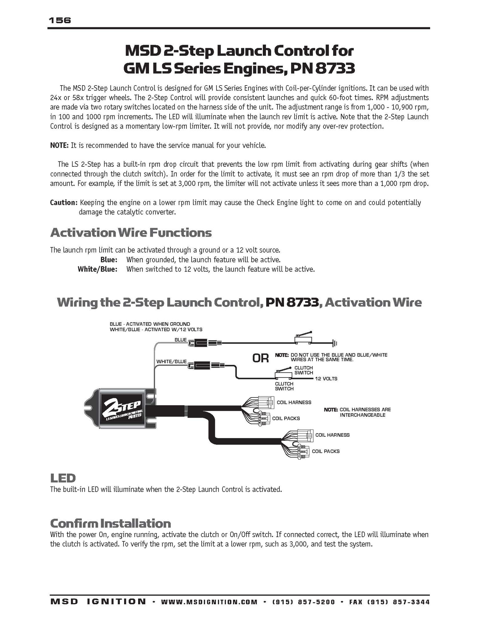
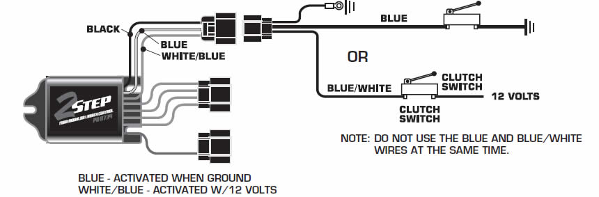
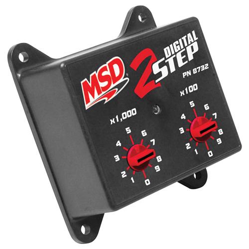
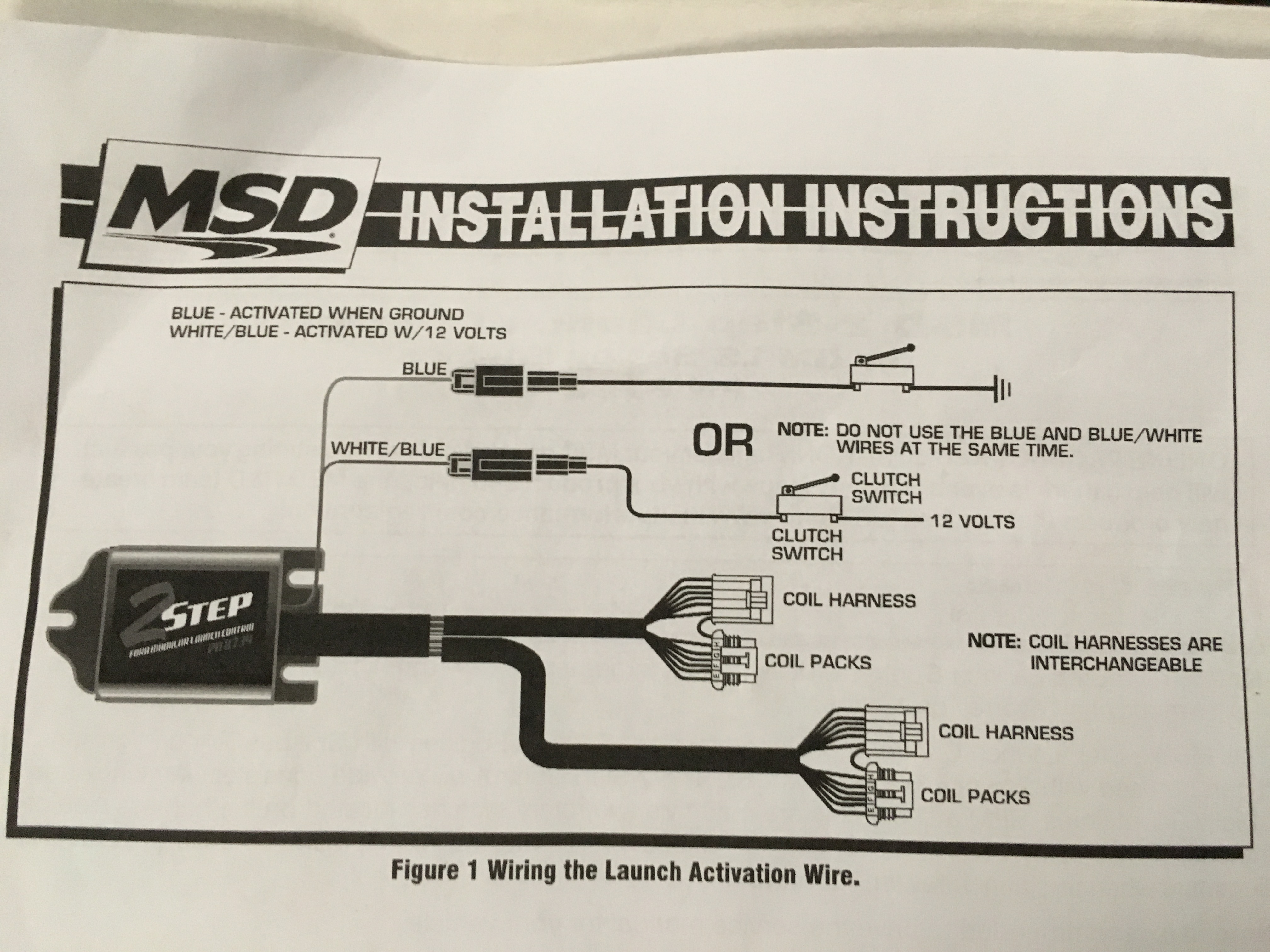
Msd 3 step wiring diagram. MSD Three-Step Module Selectors. MSD 3-step module selectors are designed for great versatility. They feature three built-in rev limiters--one for burnout, one for starting line launch, and one for high end. These selectors use the MSD plug-in rpm modules. Warranty. Recommended for You. Msd Pn 8970 Wiring Diagram. That is why we have assembled the MSD Ignition Wiring Diagrams and Tech Notes Book. 3-Stage Retard, PN , and Multi-Step Retard, PN Red. Page 1. 3-Stage Retard PN IMPORTANT: Read the instructions before attempting the installation. Parts Included: 1 - 3-Stage Retard Control 4 - Mounting. MSD Module Selectors Two Step, PN 8739 Three Step, PN 8737 Parts Included: 1 - Module Selector 4 - Mounting Screws 1 - Parts Bag, Wiring Terminals Note: Do ... The MSD 2-Step Launch Control is designed for Ford Modular Engines with Coil-on-Plug ignitions. ... Figure 3 Wiring the Launch Activation Wire. ACTIVATES WITH 12 VOLTS OR GROUND WHITE BLUE BLUE GROUND TAN RED GRAY BLACK NOTE: IF THE LED DOESN'T TURN ON, AS DETAILED IN STEP 5, FOLLOW THIS DIAGRAM BY SWAPPING THE 8 PIN CONNECTORS. WHITE BLUE BLUE ...
Msd 3 Step Wiring Diagram Msd 7al 3 Diagram Wiring Diagram today is one of the pictures that are related to the picture before in the collection gallery, uploaded by autocardesign.org.You can also look for some pictures that related to Wiring Diagram by scroll down to collection on below this picture. If you want to find the other picture or article about Msd 3 Step Wiring Diagram Msd 7al 3 ... Note: The MSD 7AL-3 will retard the ignition timing approximately 4° compared to other MSD Ignitions. After installation, the timing should always be checked and adjusted at idle and total timing. RAS ON/OFF Figure 5 Primary Wiring to a Mallory Unilite Distributor. NOTE: ALL 3-WIRE MALLORY DISTRIBUTORS CONNECT THIS WAY. The following diagrams show the installation to a Mallory and an Accel bEI distributor .Jul 06, · I have the MSD 7AL-3 / Will be running 2 foggers and a schematron.org got a Eldebrock Progressive ' and needed to know the best wiring/diagram would be for this? The 3-Step Module Selector switches between three modules. ACTIVATION WIRES. Module 2. Module 1. Module 3. This is the default module. It is active when no ...
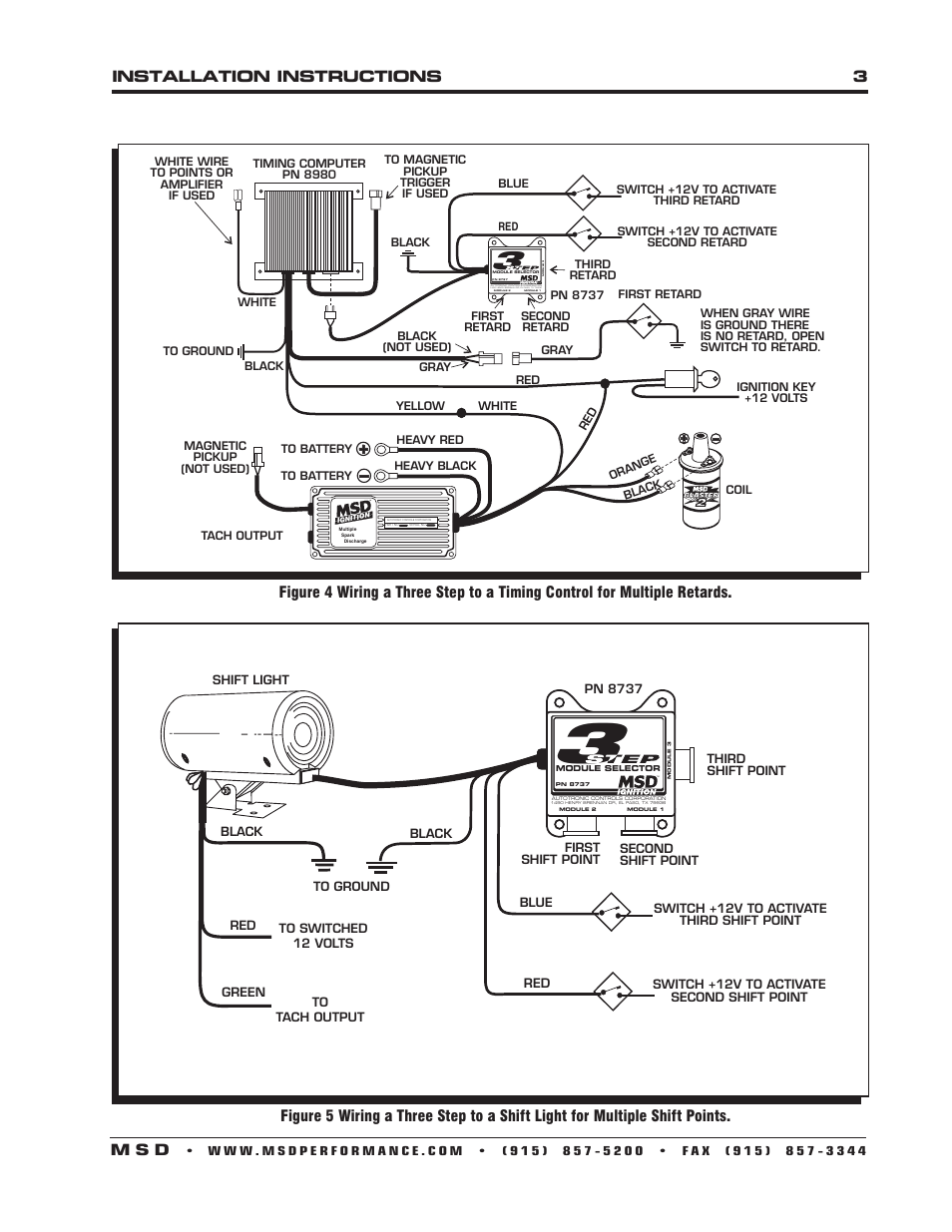
Here is the install of the MSD 3 Step... This one is for the analog 6AL box that's older. MSD also makes one of these for the digital 6AL box.Thanks For Wa... Msd 6al 6425 Wiring Diagram. MSD 6AL Ignition Module w/ Rev Control - Installation Instructions The supplied wiring isn't very long, so I added about 4 feet to each wire. When you add. MSD Digital 6AL Highlights - PN When viewing the wiring diagram for the 6AL and Digital 6AL, you'll notice they share a striking. Msd 2 Step Wiring Diagram. Msd 8739 rpm module selector installation instructions manualzz 2 step wiring question help yellow bullet forums mounting 8732 rev control for digital 6al user manual page 4 ignition pdf manualslib will a work with transmission ford mustang two stangnet pages also 8737 three and install rx7club com mazda rx7 forum ... figure 5 wiring a three step to a shift light for multiple shift points. shift light black to ground red green to switched 12 volts to tach output red blue switch +12v to activate second shift point switch +12v to activate third shift point pn 8737 black first shift point third shift point second module 2 module 1 pn 8737
beige painted building
If you already have the MSD 6AL connected then here is the Multi-Step Retard PN 8972 Wiring. Black - To ground Red - To Switched 12 volts (Ignition on/off) Yellow - To white wire on MSD 6AL Violet - To Starter Solenoid Switched 12 volt wire White - To Points or amplifier trigger wire Violet/Green - To Distributor Mag (+) and Mag (-)
Msd Two Step Wiring Diagram - ZYNRA-ZINXIE
3. After cutting the loop(s), turn the wire ends away from each other so they cannot come into contact. Install the cover and screw. WIRING GENERAL WIRING INFORMATION Wire Length: All of the wires of the MSD Ignition may be shortened as long as quality connectors are used or soldered in place.

aerial view of city buildings during night time
3. After cutting the loop(s), turn the wire ends away from each other so they cannot come into contact. Install the cover and screw. Note: MSD offers Ignition Controls for odd-fire 6-cylinder engines: 6A, PN 6246 and the 6T, PN 6446. WIRING GENERAL WIRING INFORMATION Wire Length: All of the wires of the MSD Ignition may be shortened as long as ...
Msd Pn 8970 Wiring Diagram
Page 1 MSD Module Selectors Two Step, PN 8739 Three Step, PN 8737 Parts Included: 1 - Parts Bag, Wiring Terminals 1 - Module Selector 4 - Mounting Screws Note: Do NOT use solid core spark plug wires with any MSD component.; Page 2 INSTALLATION INSTRUCTIONS REV LIMITER STEP MODULE SELECTOR PN 8739 BLACK AUTOTRONIC CONTROLS CORPORATION 1490 HENRY BRENNAN DR, EL PASO, TX 79936 MODULE 2 MODULE 1 ...

Msd 2 Step Wiring Diagram - General Wiring Diagram
I have it conected to my 2 step so the transbrake and 2 step are activated at the same time. The solenoid will engage and release when the rpms are low but if I push the transbrake button and put the peddle to the floor the car comes up on the 2 step but when I release the button the car doesn't move. Could it be low amperage or just a wiring ...

Msd 3 Step Wiring | Wiring Diagram Database
STEP CONTROL WIRES GRAY This wire activates the Step Retard when it is removed from ground. Note: If the Step Retard is not going to be used, ... Figure 10 Wiring an MSD 10 PLUS with a Mag Pickup. INSTALLATION INSTRUCTIONS MSD IGNITION • www.msdignition.com • (915) 857-5200 • FAX (915) 857-3344

Msd 2 Step Wiring Diagram - Wiring Diagram Schemas
4 INSTALLATION INSTRUCTIONS AUTOTRONIC CONTROLS CORPORATION • 1490 HENRY BRENNAN DR., EL PASO, TEXAS 79936 • (915) 857-5200 • FAX (915) 857-3344 WIRING GENERAL WIRING INFORMATION Wire Length: All of the wires of the MSD Ignition may be shortened as long as quality connectors are used or soldered in place.

6ls Msd Wiring Diagram - easywiring
A wiring diagram is a type of schematic which uses abstract photographic icons to show all the interconnections of elements in a system. Msd 6al 2 ignition control pn 6421. Msd 6al with 2 step wiring diagram use wiring diagram msd 3 step wiring diagram schema diagram database. Symbols that represent the components in the circuit as well as ...

20 Awesome Msd Retard Box Wiring Diagram
figure 3 basic three step installation. t a c h c+ c-ign pts m+ m-ground rpm to ground to 12v module 2 - active with no voltage. module 1 - active with 12 volts on red wire. module 3 - active with 12 volts on blue wire. this module will also be active if 12 volts are supplied to the red and blue wires. to 12v clutch switch msd micro switch pn 8820 blue red black
Wiring Diagram: 32 Msd 7al 2 Wiring Diagram
The MSD 6014 LS Ignition controller works with 24x/1x, 58x/4x and crank/cam configurations. It auto detects the correct configuration based on the reluctor wheel pattern, so there is no need to select one. It provides six pre-programmed (non-editable) timing tables for stock engines, three customizable 3-D tables and one customizable timing plot.
Msd 7al3 Wiring Diagram
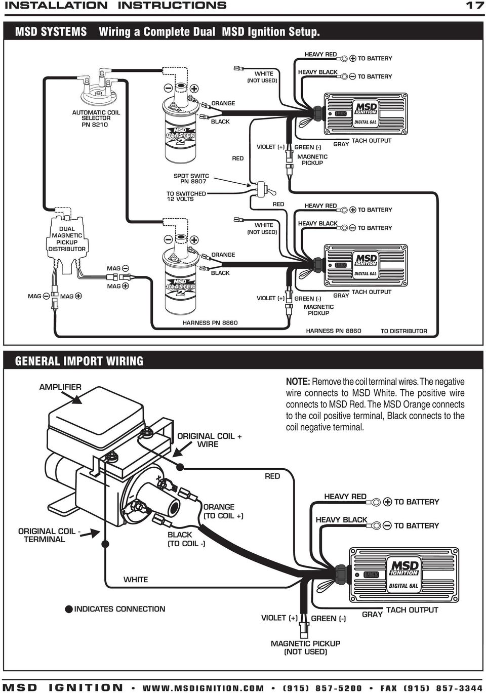
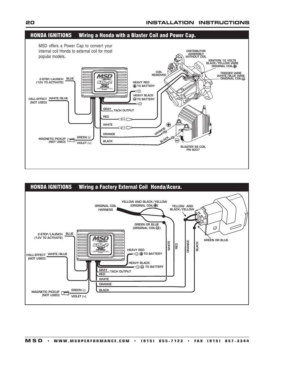
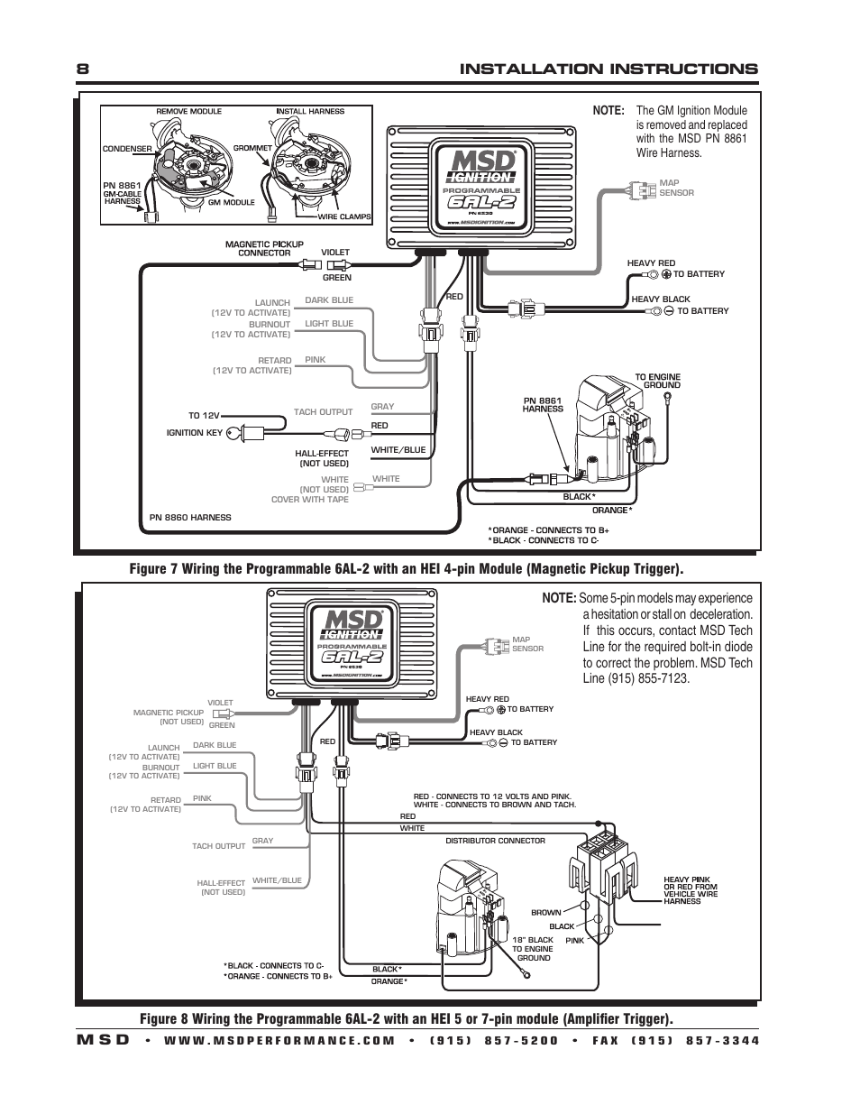
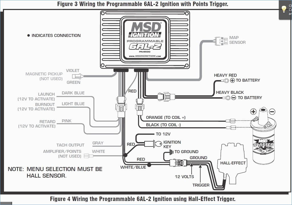
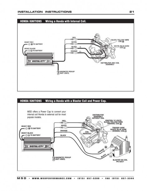
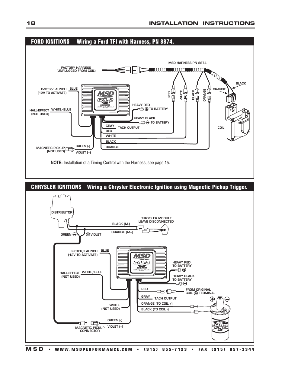
There are three circuits that can be used to trigger the MSD Ignition; a Points circuit (the White wire), a Magnetic Pickup circuit (the Green and Violet wires), and a Hall-effect wire (White/Blue). Only one circuit will be used at a time.

Msd 7al-3 Wiring Diagram
Module 2: This is the default module. It is active when no voltage is present. on the other wires. Module 1: Active when 12 volts are applied to the Red Wire. Module 3: Active when 12 volts are applied to the Blue Wire. (3-Step Only) Note: If 12 volts are applied to the Red and Blue wires at the same time, Module 3 will be active. Top.

20 Beautiful Msd 7Al 2 Wiring Diagram
Msd Distributor Wiring Diagram. January 13, 2019. April 12, 2020. · Wiring Diagram. by Anna R. Higginbotham. msd distributor wiring diagram - You will need a comprehensive, skilled, and easy to know Wiring Diagram. With this sort of an illustrative manual, you are going to be able to troubleshoot, stop, and total your projects without ...

man riding blue and white motorcycle on road during daytime
wire the 2-Step rev limit and the LED will turn off. 3-STEP If you prefer to have three different rev limits, a second PN 8732 could be used to provide a third rev limit, such as for use during the burnout. MSD • WWW.MSDPERFORMANCE.COM • (915) 855-7123 • FAX (915) 857-3344 ONLINE PRODUCT REGISTRATION: Register your MSD product online.

38 Msd 8732 Wiring Diagram - Wiring Diagram Online Source
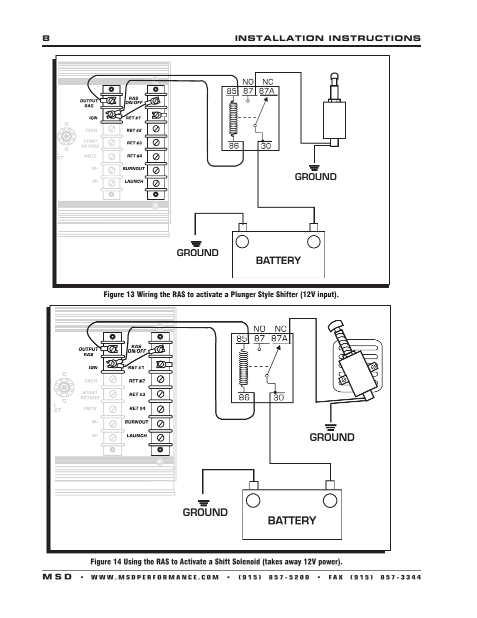
WIRING THE UNIT Follow the wiring diagram supplied. If your RPM switch or Timer supplies a "Normally Open Ground" connect the trigger wire from your device to post 86 on the relay. Supply post 87 and 85 with 12V+, with a 12 gauge wire. Connect post 30 to the solenoid.
35 Msd 2 Step Wiring Diagram - Wiring Diagram Database
Mar 07, 2019 · msd 3 step wiring diagram wiring diagram datasource. Architectural wiring diagrams play in the approximate locations and interconnections of receptacles, lighting, and remaining electrical facilities in a building. Interconnecting wire routes may be shown approximately, where particular receptacles or fixtures must be on a common circuit.
MSD 7AL Box Instructions Video Book - YouTube
INSTALLATION INSTRUCTIONS 3 AUTOTRONIC CONTROLS CORPORATION • 1490 HENRY BRENNAN DR., EL PASO, TEXAS 79936 • (915) 857-5200 • FAX (915) 857-3344 Figure 4 Wiring an MSD 6 Series Ignition with a Mag Pickup. Figure 5 Wiring an MSD 7 Series Ignition with Points/Amplifier.
40 Msd 3 Step Wiring Diagram - Wiring Diagram Online Source
Note: The MSD 7AL-3 will retard the ignition timing approximately 4° compared to other MSD Ignitions. Read online or download PDF • Page 9 / 12 • MSD 7AL-3 Ignition Control Installation User Manual • MSD For the car. Choose the appropriate wiring diagram from the reverse side and wire as shown.

33 Msd 3 Step Wiring Diagram - Wiring Diagram List
MSD 2 Step Clutch Wiring Diagram - Chevelle Tech
8installation instructions m s d | MSD 6530 Digital ...

Msd 8680 Wiring Diagram

Msd 3 Step Wiring | Wiring Diagram Database

architectural photography of white, brown, and black bridge
Msd 7al3 Wiring
33 Msd 3 Step Wiring Diagram - Wiring Diagram List
Msd 2 Step Wiring Diagram - Wiring Diagram Schemas
31 Msd 7al 2 Wiring Diagram - Wiring Diagram List

Msd 2 Step Wiring Diagram - General Wiring Diagram

27 Msd Street Fire Wiring Diagram - Wire Diagram Source ...

Msd 3 Step Wiring Diagram Database
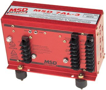
MSD 7AL-3
MSD 2 Step Rev Controller for 6AL Box 8732 - LMR.com
Need help wiring MSD 2-step - PerformanceTrucks.net Forums
Msd 6al Hei Wiring Diagram Collection | Wiring Diagram Sample

Msd 2 Step Wiring Diagram - Hanenhuusholli

Msd 3 Step Wiring | Wiring Diagram Database
Msd Ignition Box Wiring Diagram - Wiring Diagram Schemas
Msd Pn 6520 Wiring Diagram | Best Diagram Collection
Msd 2 Step Wiring Diagram. msd two step wiring diagram ...
Installation instructions 3 m s d | MSD 7330 7AL-3 ...
0 Response to "41 msd 3 step wiring diagram"
Post a Comment