40 shunt trip breaker diagram
Tutorial for wiring a shunt trip QO™ (and QOB) Circuit Breaker. Shunt trips (accessories) in QO™ breakers are factory installed only and can not be added to ... Wiring Diagram Pics Detail. 1 A shunt trip breaker is a breaker with a solenoid to trip when power is applied to the solenoid. 6 Install circuit breaker. This is a very simple wiring diagram. Shunt breaker wiring diagram Wiring Diagram for Shunt Trip Breaker Copy Best Shunt Trip Breaker Wiring Diagram 71 for Chromalox Heater.
Controlling the Masterpact MTZ Circuit Breaker Open/Closed Status Selection of Coils Shunt Close (XF), Shunt Trip (MX), and Undervoltage Release (MN) with Diagnostic and Communicating Coils

Shunt trip breaker diagram
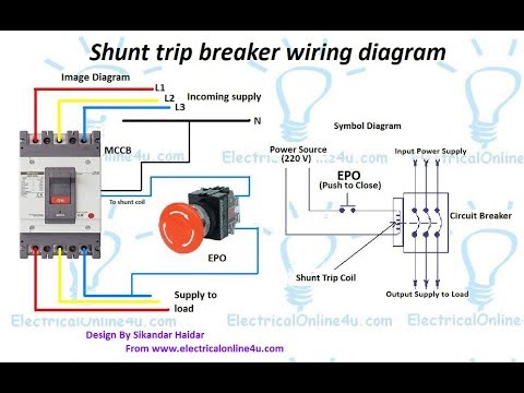
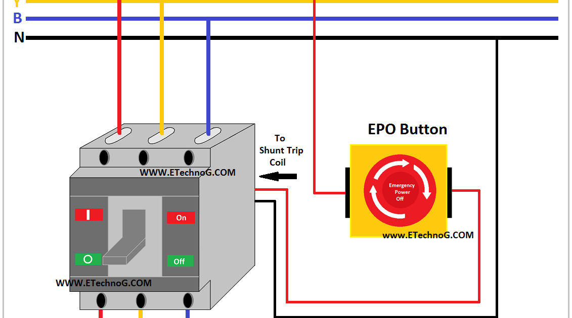
Oct 28, 2016 · Shunt Trip Breaker Wiring Diagram with EPO Button. In this post i am just tell you about wiring of single EPO button with shunt trip MCCB breaker. In industrial state, Electric operator duty is to operate the machinery and his duty is on the front of Main panel board. Wiring Diagram for Shunt Trip Breaker- One of the most difficult automotive repair tasks that a mechanic or fix shop can undertake is the wiring, or rewiring of a car's electrical system.The hardship really is that every car is different. as soon as frustrating to remove, replace or repair the wiring in an automobile, having an accurate and detailed Wiring Diagram for Shunt Trip Breaker is ... Wiring Diagram For Shunt Trip Breaker Circuit, Diagram, Wire, The Unit, Chart. L. Lim Johnny. 317 followers. More information.
Shunt trip breaker diagram. shunt breaker wiring diagram - What is a Wiring Diagram? A wiring diagram is a simple visual representation in the physical connections and physical layout associated with an electrical system or circuit. It shows how the electrical wires are interconnected and will also show where fixtures and components may be coupled to the system. The shunt trip, shown in kit form in Fig. 2-1, is installed in the left accessory mounting cavity of a 2, 3, or 4-pole circuit breaker. A shunt trip must be installed in the circuit breaker before the cir-cuit breaker is mounted in an electrical system. To install the shunt trip, perform the following procedures: Wiring Diagrams for MasterPact NW Circuit Breakers. NOTE: All diagrams show circuit breaker open, connected and charged. A. Do not remove factory-installed jumpers between Z3, Z4 and Z5 unless ZSI is connected. B. Do not remove factory-installed jumper between T1 and T2 unless neutral CT is connected. Do not install jumper between T3 and T4. C. LarryFine. In simple terms, a shunt-trip breaker is a breaker that can be tripped by remote control. There is a coil inside the breaker that will trip the breaker upon either energization or de-energization, depending on the model and purpose. A couple of years ago, we had to replace the 225a, 3p main breaker for one panel in a switch-gear stack.
Shunt Trip (MX) and Undervoltage Trip (MN) A voltage release can be used to trip the circuit breaker using a control signal. Table 81: Shunt Trip and Undervoltage Trip Applications Shunt Trip (MX) • Trips the circuit breaker when the control voltage rises above 70% of its rated voltage • Impulse type 20 ms or maintained control signals In this video i complete explain the shunt trip breaker wiring diagram or installation of shunt trip circuit breaker. In this video i also shown with video ... Collection of square d shunt trip breaker wiring diagram. AC device that we use in our homes generally have a limit to handle the current and voltage.These threshold voltage and current are called the device rating, and are the measurements given by the manufacturers in the range of which the device will work properly. Siemens Shunt Trip Breaker Wiring Diagram. Broadly speaking, there are three major types of circuit breakers: standard, ground fault circuit interrupters (GFCIs), and arc fault circuit interrupters (AFCIs). While the circuit is open, Hystrix redirects calls. The working of the electrical equipment used in the substation is explained below in ...
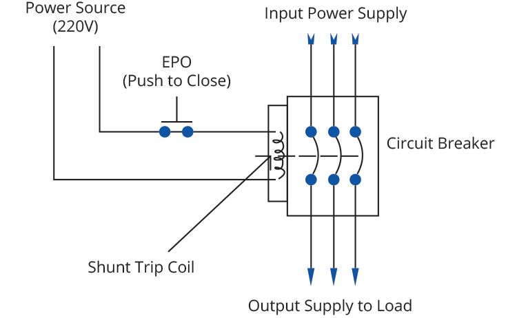
Apr 05, 2019 · Shunt Trip Breaker Wiring Diagram – eaton shunt trip breaker wiring diagram, elevator shunt trip breaker wiring diagram, ge shunt trip breaker wiring diagram, Every electric arrangement is made up of various distinct parts. Each part should be placed and connected with other parts in particular way. If not, the arrangement won’t work as it should be. The shunt trip breaker is a combination of the shunt trip accessory and the main circuit breaker. This installs on the main breaker to add protection to your electrical system. This adds security to your electrical system as it manually or automatically cuts the electric supply in your circuit. This accessory can help prevent short circuits and ... Shunt trip breaker wiring diagram explanation readingrat for throughout square d shunt trip circuit breaker wiring diagram image size 438 x 297 px and to view image details please click the image. March 3 2019 by larry a. It reveals the components of the circuit as simplified forms and the power and also signal links in between the tools. This is a very simple wiring diagram. You can see just there is an EPO or Emergency Power Off button is connected in series with the shunt trip coil of the MCCB. It is a normally open switch, when you push, it will close the circuit. So the shunt trip coil will get power supply and it will trip the MCCB. Note that, the shunt trip coil is rated ...
Shunt trip breakers - ECN Electrical Forums
Siemens Sentron™ Series circuit breakers are available in nine frame sizes: ED the ED frame has a maximum continuous current range of 15 to amps. case switch, instantaneous magnetic trip circuit breaker (motor are shown in the following chart: . shunt trip device consists of a coil in series with a limit switch.
Standard tripping schemes and trip circuit supervision ...
shunt trip, and overcurrent trip switch warning (1)only qualified electrical personnel should be permitted to work on the equipment. (2)always de-energize primary and secondary circuits if a circuit breaker cannot be removed to a safe work location. (3)drawout circuit breakers should be levered (racked) out to the disconnect position.
Elevator Shunt Trip – Fire Alarm Requirements Here are the ...
Nov 09, 2021 · In the above MCCB shunt trip breaker wiring diagram. 120v Shunt Trip Wiring Diagram wiring diagram is a simplified normal pictorial representation of an electrical circuit. Emergency Power Off EPO is the capability to. Shunt trip breaker wiring diagram this post is about the single wiring diagram of mccb shunt trip breaker.

The common wire on the normally open and normally closed ...
Ge Shunt Trip Breaker Wiring Diagram A shunt trip must be installed in the circuit breaker before the cir- cuit breaker is mounted in an electrical system Route wiring to meet installation requirements. GE Industrial Systems makes no representation or warranty, expressed, implied, ..
New to shunt trips and these hoods. It's a captive aire hood ...
Jun 18, 2018 · DOWNLOAD. Wiring Diagram Images Detail: Name: siemens shunt trip breaker wiring diagram – Siemens Shunt Trip Breaker Wiring Diagram Unbelievable Heavenly And. File Type: JPG. Source: techreviewed.org. Size: 737.05 KB. Dimension: 3521 x 2290. DOWNLOAD. Wiring Diagram Pics Detail:
Shunt Trip Breaker Wiring Diagram In Urdu & Hindi || How To Install A Shunt Trip Breaker
Understanding the Shunt Trip Breaker Wiring Diagram. Before wiring your shunt trip breaker to your safety control system or switch, you need to first understand its wiring diagram. This is a crucial part of the installation—that’s why you can’t skip it and need to be more careful with it.
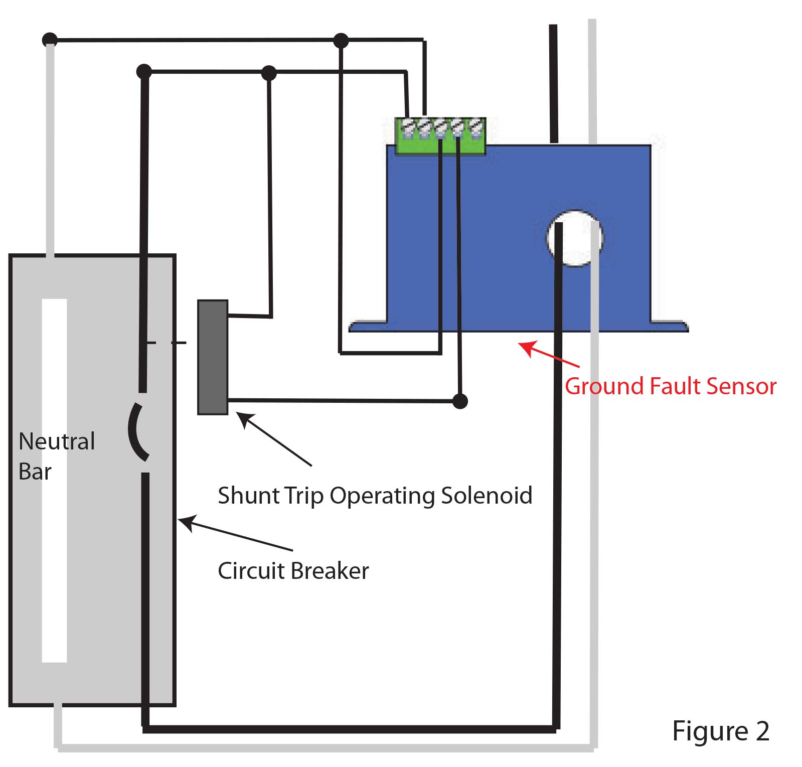
Monitoring Ground Faults of Heat Trace Systems - NK Technologies
Apr 06, 2019 · Shunt Trip Breaker Wiring Diagram For Ansul System - You almost certainly already know that square d shunt trip breaker wiring diagram has become the hottest topics over the internet today. Based on the information we took from google adwords, square d shunt trip breaker wiring diagram has very much search online web engine.
Shunt Trip Breaker Wiring Diagram Explanation
Diagram. CHST Eaton Cutler-Hammer 1P 20A Shunt Trip Breaker. Type CH 3/4-Inch Standard Circuit Breaker, Single-Pole, 20A, /V, 10 Kaic, (1) # The Shunt Trip allows a circuit breaker to be tripped remotely by applying a voltage to the wire leads. The unit Figure Shunt Trip Connection Diagram. Instruction Leaflet IL 29CG.

Elevator Shunt Trip Requirements and Codes | Fire Alarms Online
Elevator Shunt Trip - Fire Alarm Requirements Here are the requirements for heat detector placement, monitoring of power and wiring diagram from 1999 NFPA 72: 3-9.4.1* Where heat detectors are used to shut down elevator power prior to sprinkler operation, the detector shall have both a lower temperature rating and a higher

Flux Shunt Trip Actuator Interface and Breaker Reset ...
The breaker shunt trip coil is controlled by the emergency switch. Shunt trip breaker wiring diagram this post is about the single wiring diagram of mccb shunt trip breaker. Here is a picture gallery about square d shunt trip circuit breaker wiring diagram complete with the description of the image please find the image you need.

How to Wire a Shunt Trip Breaker Wiring Diagram (DIY Guide)
This diagram can help clear up the wiring in of fire alarm modules and relays. using an addressable relay module (FRM-1) to operate the shunt trip breaker directly. Labels: elevator equipment, elevator machine room, elevator recall, Waterflow, Backflow, PIV and OS&Y · Sprinkler Waterflow Flapper. On all of the fire systems I have wired, we put ...
How to connect shunt trip breakers
Wiring Diagram For Shunt Trip Breaker Circuit, Diagram, Wire, The Unit, Chart. L. Lim Johnny. 317 followers. More information.
How to wire the circuit breaker shunt trip? | Nader Circuit ...
Wiring Diagram for Shunt Trip Breaker- One of the most difficult automotive repair tasks that a mechanic or fix shop can undertake is the wiring, or rewiring of a car's electrical system.The hardship really is that every car is different. as soon as frustrating to remove, replace or repair the wiring in an automobile, having an accurate and detailed Wiring Diagram for Shunt Trip Breaker is ...
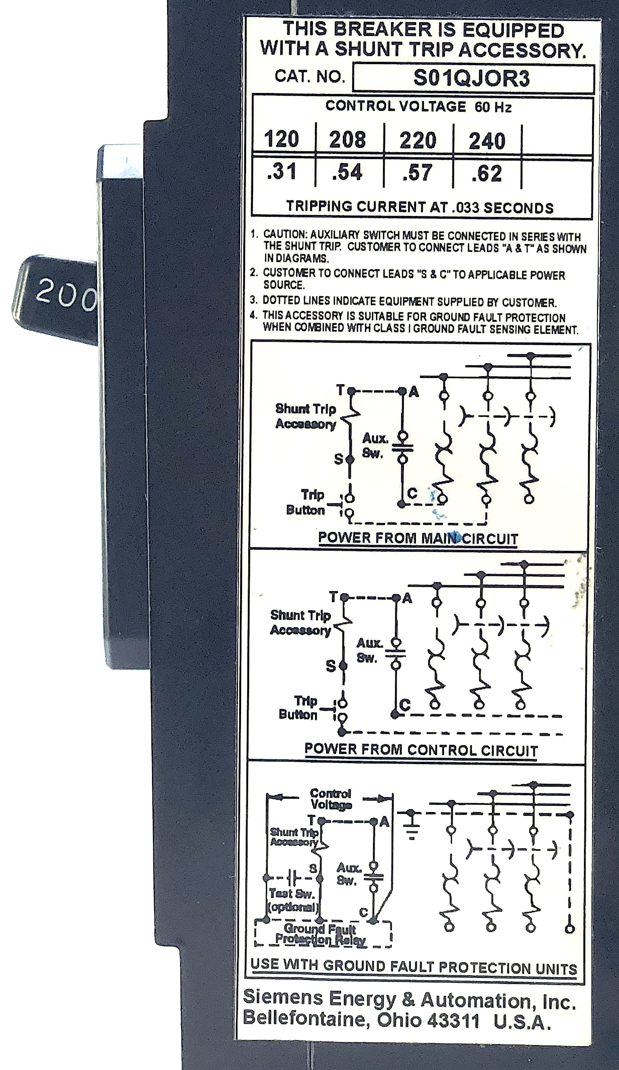
Siemens 3 Pole 200 Amp 240 Vac Circuit Breaker w/Shunt Trip ...
Oct 28, 2016 · Shunt Trip Breaker Wiring Diagram with EPO Button. In this post i am just tell you about wiring of single EPO button with shunt trip MCCB breaker. In industrial state, Electric operator duty is to operate the machinery and his duty is on the front of Main panel board.

GE Industrial THQB2130ST1 Bolt-On Mount Type THQB Miniature ...
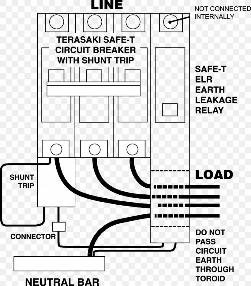
Earth Leakage Circuit Breaker Wiring Diagram Relay Fault, PNG ...

SNT1LP03K-CHGP
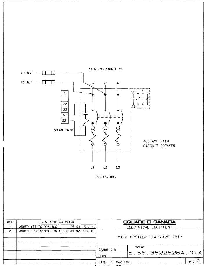
main breaker c/w shunt trip
How to Wire a Shunt Trip Breaker Wiring Diagram (DIY Guide)

I am wiring an ANSUL fire suppression system and need to know ...

What is a Shunt Trip Breaker and How Does It Work?

ASI SHT-220 MCCB Shunt Trip Module: Amazon.com: Tools & Home ...
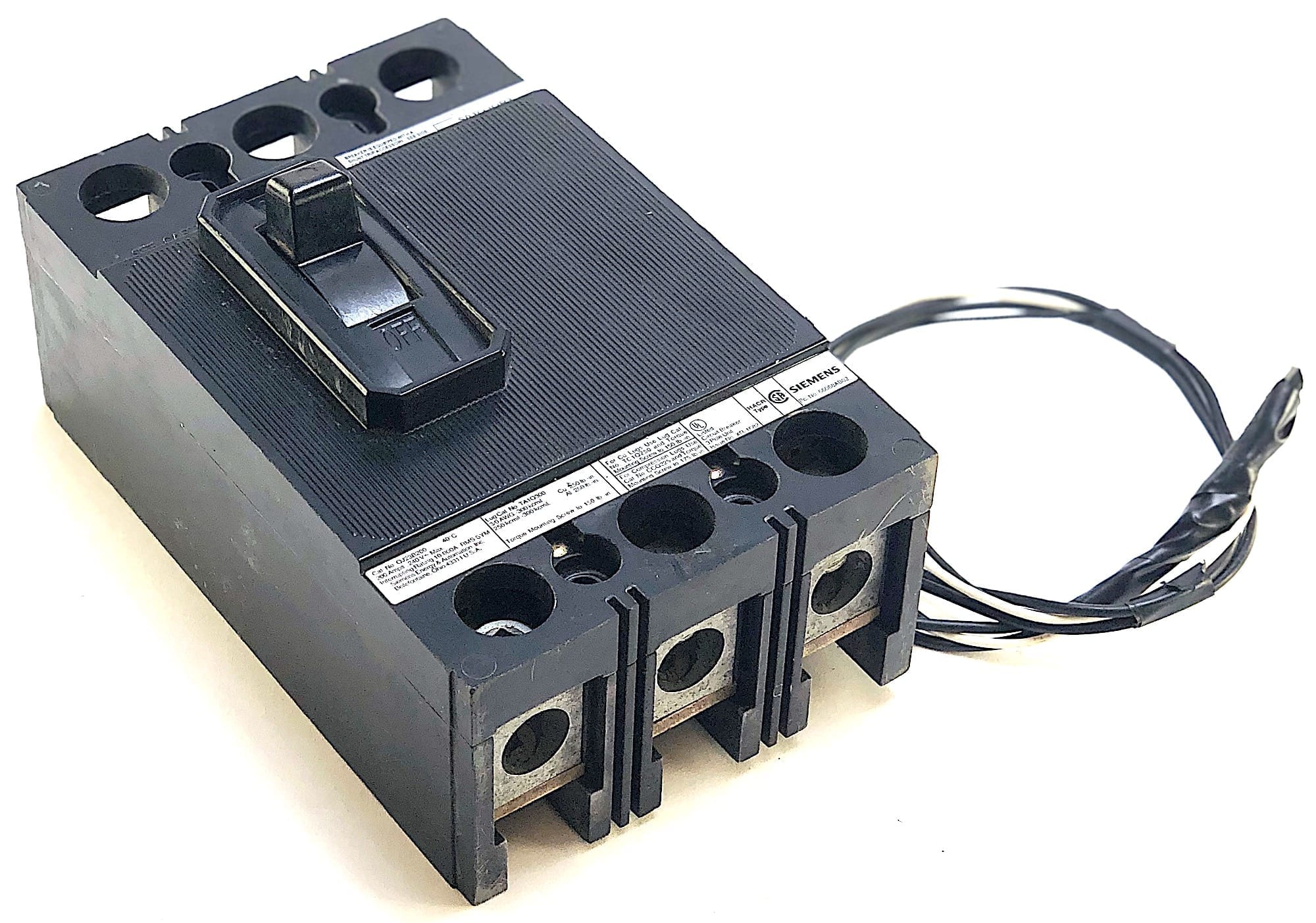
Siemens 3 Pole 200 Amp 240 Vac Circuit Breaker w/Shunt Trip ...
Shunt Trip Breaker Wiring Diagram, Connection, Circuit - ETechnoG
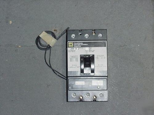
Square d KAL36200 w/shunt trip circuit breaker
BR230ST | Eaton BR thermal magnetic circuit breaker | Eaton
fusible shunt trip switch
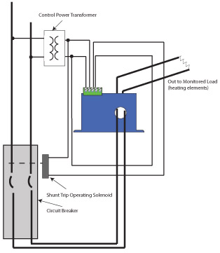
Ground Fault Protection Solutions | NK Technologies
Installation Instructions for Shunt Trip for LDB, LD, HLD ...
Enhance Your Application with MCB Accessories - c3controls

madcomics: Shunt Trip Breaker Wiring
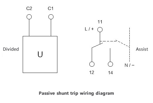
Introduction Shunt Trip (Extended Range): A device designed ...
Main Circuit Breaker Mcb Shunt Trip Circuit Breaker(spm1-1le ...
Q and M-Frame Circuit Breakers Instruction Leaflet for Shunt Trip

Shunt Trips - Shunt Trip Circuit Breakers - Relectric

Eaton CH320ST :: Breaker, 20A, 3P, 120/240V, 10 kAIC, Type CH ...
Shunt Trip – Westshore Controls
Shunt trip breaker wiring diagram, Control of mccb breaker ...
Installation Instructions for Series G N-Frame Circuit ...
Introduction Shunt Trip (Extended Range): A device designed ...
0 Response to "40 shunt trip breaker diagram"
Post a Comment