45 two force member free body diagram
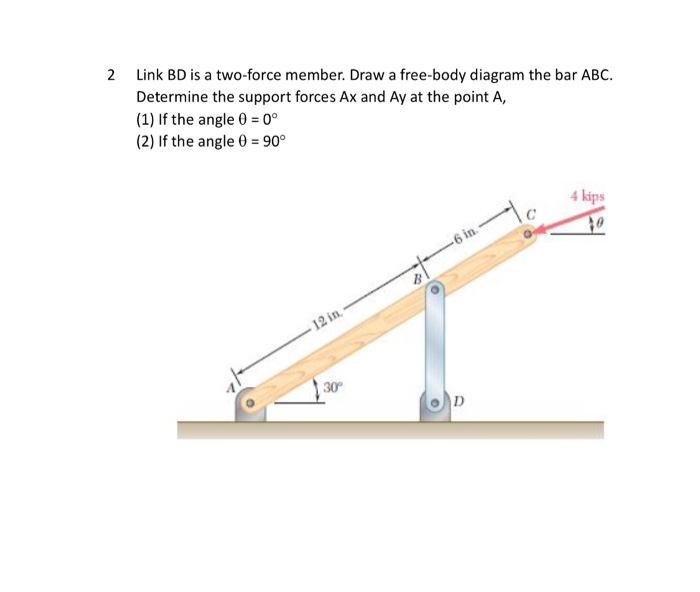
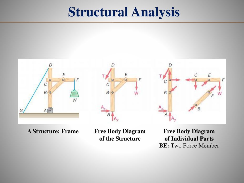
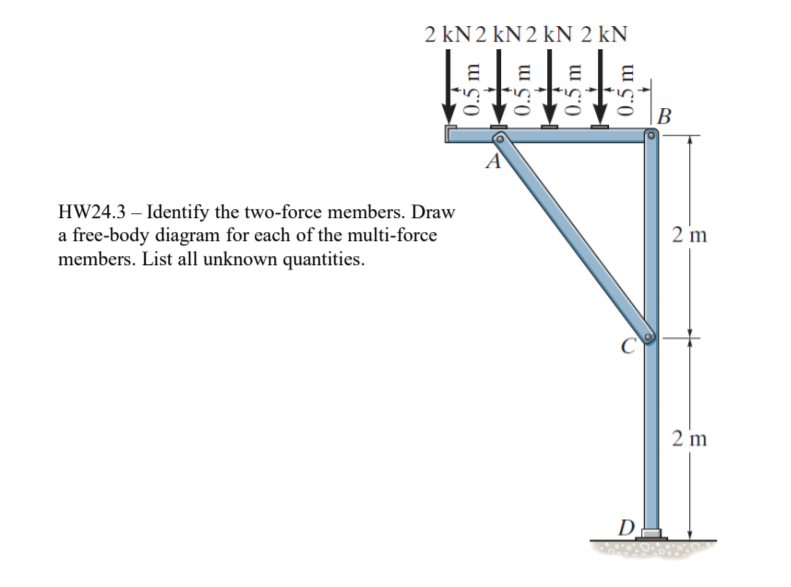
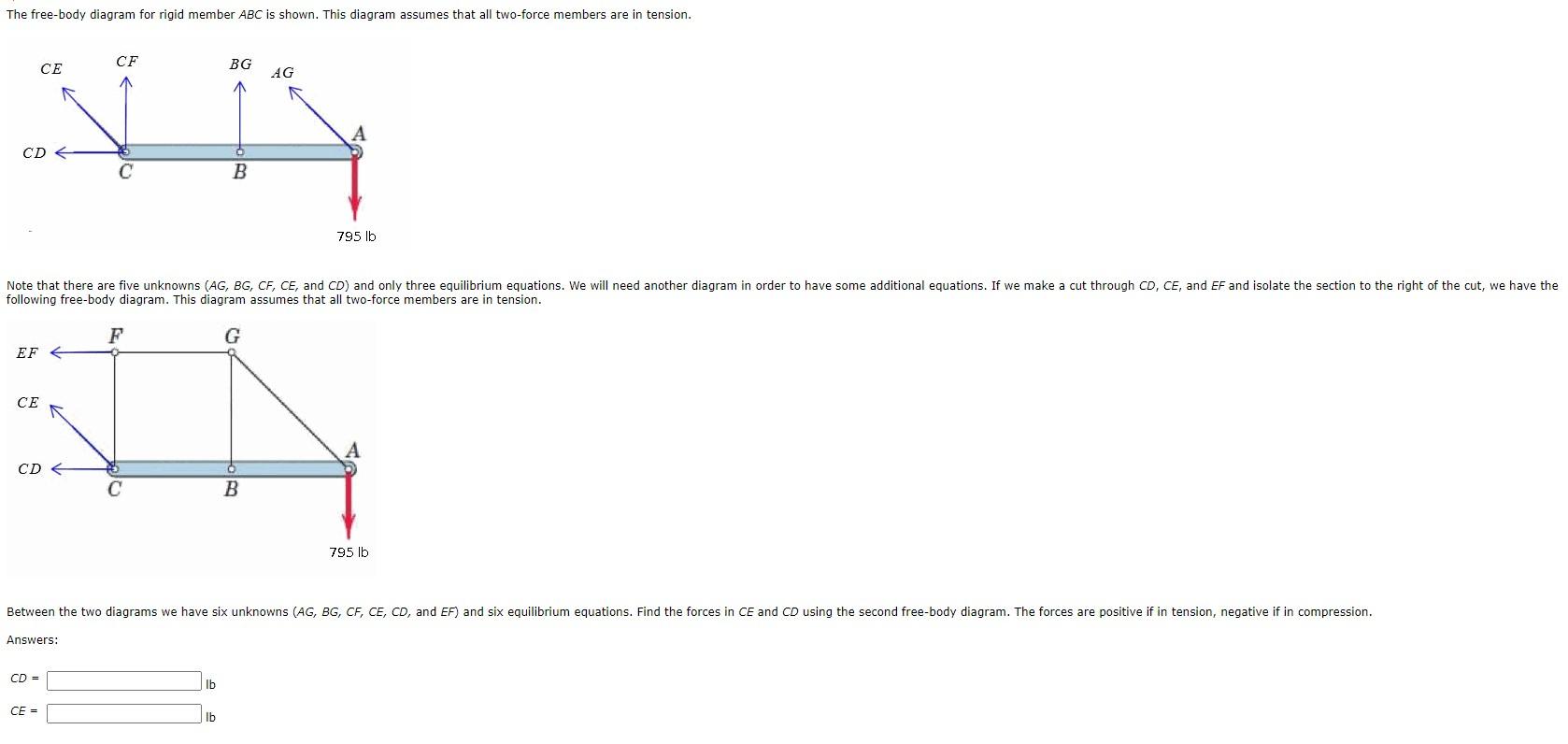
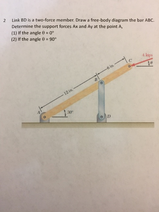
note that BC is a two-force membersince only two forces act on it. For this reason, the reaction at C must be horizontal as shown. Since BA and BD are also two-force members, the free-body diagram of joint B is shown in Fig. 1-7c.Again, verify the magnitudes of the computed forces and Free-Body Diagram.Using the result for the left section AG a) Show that DB is a two-force member? Draw a qualitatively correct extended free body diagram of DB. b) Draw an extended free body diagram of member ABC. c) Write the three equilibrium equations for member ABC( namely Fnet,x=0 , Fnet,y=0 and Mnet/p,z=0). Make clear the choice of your point P for the moment equation.
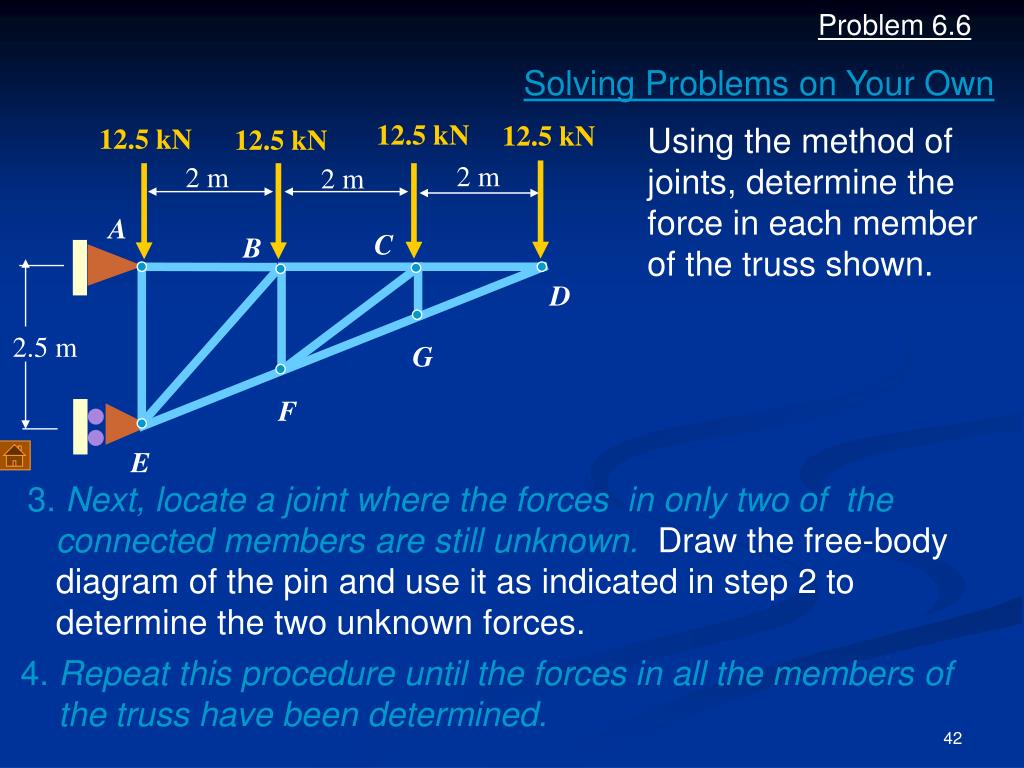
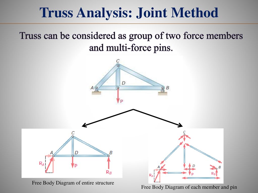
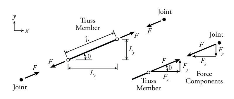
1. Draw a Free Body Diagram (FBD) of the entire truss cut loose from its supports and find the support reactions using the equations of equilibrium (we will see that for some truss structures this step is not always necessary); 2. Draw a FBD of a truss joint that has no more than two unknowns and use the two equations of equilibrium to find the two unknown truss member forces;

Two force member free body diagram
Chapter 5.4one example solving a problem of a member being supported by a cable using a free-body diagram and calculating the support reactions A free-body | Chegg.com. Engineering. Mechanical Engineering. Mechanical Engineering questions and answers. Consider the frame shown (Figure 2) . A free-body diagram of member BC is shown (Figure 3) . What forces should not appear in this diagram? Question: Consider the frame shown (Figure 2) . Free online beam calculator for generating the reactions, calculating the deflection of a steel or wood beam, drawing the shear and moment diagrams for the beam. This is the free version of our full SkyCiv Beam Software. This can be accessed under any of our Paid Accounts, which also includes a full structural analysis software.
Two force member free body diagram. 4.2 Free Body Diagrams The free body diagram is a depiction of an object or a body along with allthe external forces acting on it. • Choose and draw the body (with dimensions). Carefully define its boundaries. • Imagine the body in its current state and how it interacts with its surroundings. • Draw ALL the external forces acting on the ... Consider the following free body diagram of a two-force member. Inasmuch as the stress σ acts in a direction perpendicular to the cut surface, it is referred to as a NORMAL stress. Thus, normal stressed may be either tensile or compressive. Our sign convention for normal stresses is: Tensile stresses are positive (+) Example 8 : A system with two blocks, an inclined plane and a pulley. A) free body diagram for block m 1 (left of figure below) 1) The weight W1 exerted by the earth on the box. 2) The normal force N. 3) The force of friction Fk. 4) The tension force T exerted by the string on the block m1. B) free body diagram of block m 2 (right of figure below) Everything that is needed to solve a force system is included on the FBD. Free body diagrams may not seem necessary in the relatively simple current applications, but as problems become more complex, their usefulness increases. The following is the process for determining the reaction at the wall for a cantilever beam.
Complete the free-body diagram of the two truss members by adding the forces that act on them. The upper left member is in compression and the lower right member is in tension. Compressive forces should terminate at the joint. Tensile forces should originate at the joint. Draw the vectors starting or ending at the appropriate black dots. A free-body diagram can be drawn very simply, with squares and arrows, or you can make it much more complex. The only requirement is that you or someone else looking at it should be able to understand what the diagram is telling. A free-body diagram (FBD) is a representation of a certain object showing all of the external forces that acts on it. A free-body diagram is a representation of an object with all the forces that act on it. The external environment (other objects, the floor on which the object sits, etc.), as well as the forces that the object exerts on other objects, are omitted in a free-body diagram. Below you can see an example of a free-body diagram: a) Identify any two-force members in the frame. b) Draw the overall free body diagram and the individual free body diagrams of members ACE and BCD, and pulley E. c) Determine the forces at pin C on member BCD.
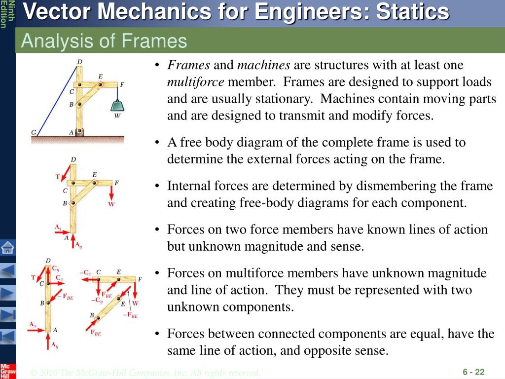
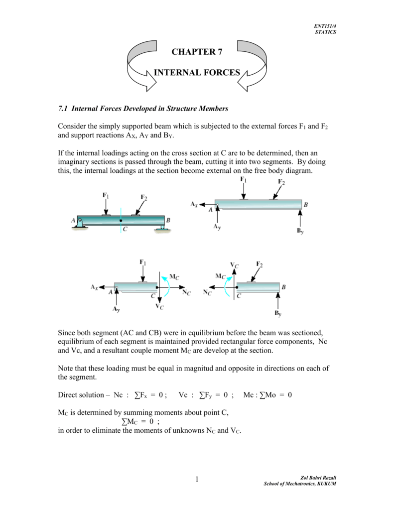
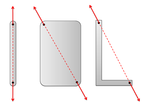
The steps include: STEP 1: Identifying two force members. STEP 2: Drawing free body diagrams of each component. STEP 3: Solving for the external forces by applying equations of equilibrium. STEP 4: Flipping the direction of negative force vectors. If you want to learn from the ground up, please watch the video!! from the member free body diagrams. ... CE is a two-force member Direction of the line joining the two points of force application determines the direction of the forces acting on a two-force member. Shape of the member is not important. ME101 - Division III Kaustubh Dasgupta 11. FREE-BODY DIAGRAMS (Section 5.2) 2. Show all the external forces and couple moments. These typically include: a) applied loads, b) support reactions, and, c) the weight of the body. Idealized model Free-body diagram (FBD) 1. Draw an outlined shape. Imagine the body to be isolated or cut "free" from its constraints and draw its outlined shape. Consider a straight two-force member AB subjected at A and B to equal and opposite forces F and -F directed along AB. Cutting the member AB at C A B C F-F F C -F A and drawing the free-body diagram of portion AC, we conclude that the internal forces which existed at C in member AB are equivalent to an axial force-F equal and opposite to F. For a two-force member which is
This engineering statics tutorial explains what two force members are and how they can be used to solve frames, machines, and truss problems. Basically, if a...

A free body diagram consists of a diagrammatic representation of a single body or a subsystem of bodies isolated from its surroundings showing all the forces acting on it. In physics and engineering , a free body diagram (force diagram, [1] or FBD) is a graphical illustration used to visualize the applied forces , moments , and resulting ...
The free body diagram of the system can be seen in the diagram below. The magnitude and the line of action of the force at F, 10 Kips, is known. and opposite to the force C of the two-force member CB. The line of action of the forces at point F and point C intersect at X. The line of action (Why is this?)
Free Body Diagram:The solution for this problem will be simplified if one realizes that member [latex]BC[/latex] is a two force member. Equations of. Results. See All Results. Question: Structural Analysis [EXP-546] Determine the horizontal and vertical components force at pins A and C of the two-member frame.
made of two force members all pin connected to each other. The method of joints: This method uses the free-body-diagram of joints in the structure to determine the forces in each member. For example, in the above structure we have 5 joints each having a free body diagram as follows Note how Newton's
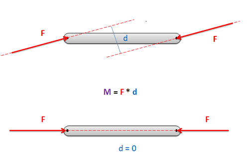
TWO-FORCE MEMBERS & THREE FORCE-MEMBERS (Section 5.4) The solution to some equilibrium problems can be simplified if we recognize members that are subjected to forces at only two points (e.g., at points A and B). If we apply the equations of equilibrium to such a member, we can quickly determine that the resultant forces at A and B must

Cantilever beams and simple beams have two reactions (two forces or one force and a couple) and these reactions can be obtained from a free-body diagram of the beam by applying the equations of equilibrium. Such beams are said to be statically determinate since the reactions can be obtained from the equations of equilibrium.

The free-body diagram of joint C indicates that the force in each member must be zero in order to maintain equilibrium. Zero-Force Members Case 2 Zero-force members also occur at joints having a geometry as joint D. Zero-Force Members Case 2
There will be cases in which the number of forces depicted by a free-body diagram will be one, two, or three. There is no hard and fast rule about the number of forces that must be drawn in a free-body diagram. The only rule for drawing free-body diagrams is to depict all the forces that exist for that object in the given situation.

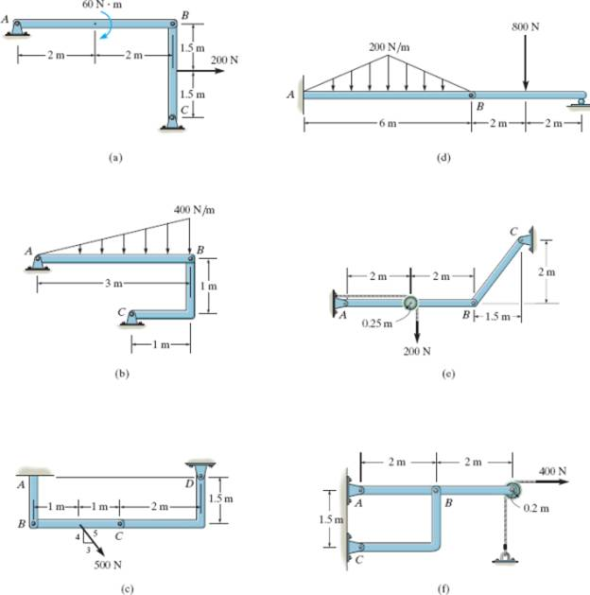
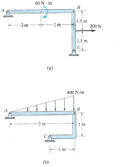
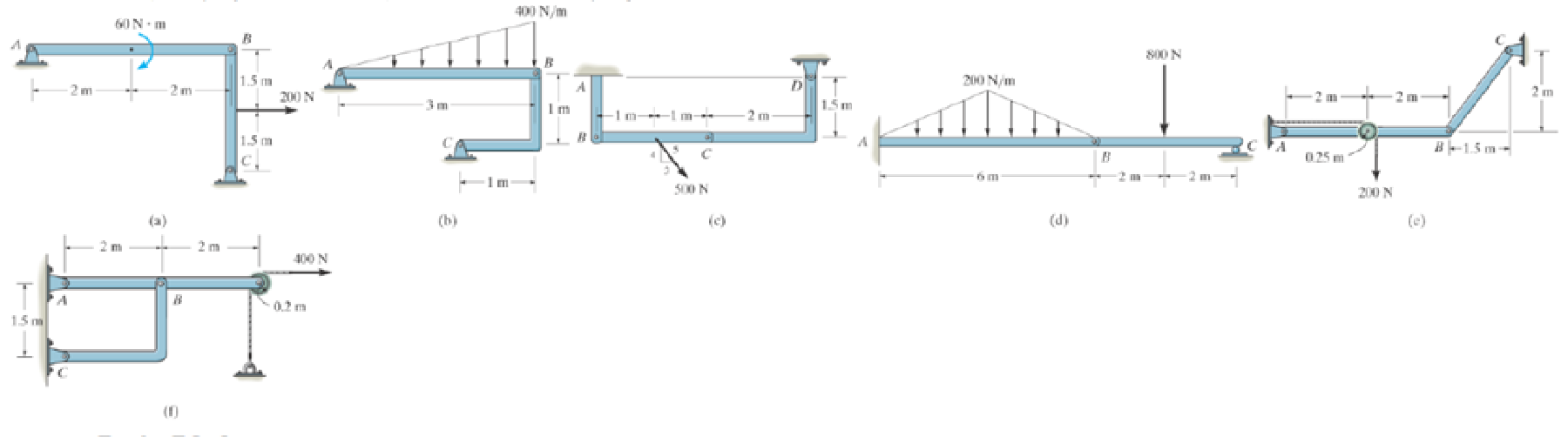
In each case, identify any two-force members, and draw the free-body diagrams of each member of the E-žme. 60 N m 1.5 m 200 N 1.5 m 400 N /m

• With equal and opposite reactions at the contact point between members, the two free -body diagrams indicate 6 unknown force components. • Equilibrium requirements for the two rigid bodies yield 6 independent equations. Department of Mechanical Engineering Members ACEand BCDare connected by a pin at Cand by the link DE.
Free online beam calculator for generating the reactions, calculating the deflection of a steel or wood beam, drawing the shear and moment diagrams for the beam. This is the free version of our full SkyCiv Beam Software. This can be accessed under any of our Paid Accounts, which also includes a full structural analysis software.
A free-body | Chegg.com. Engineering. Mechanical Engineering. Mechanical Engineering questions and answers. Consider the frame shown (Figure 2) . A free-body diagram of member BC is shown (Figure 3) . What forces should not appear in this diagram? Question: Consider the frame shown (Figure 2) .
Chapter 5.4one example solving a problem of a member being supported by a cable using a free-body diagram and calculating the support reactions


0 Response to "45 two force member free body diagram"
Post a Comment