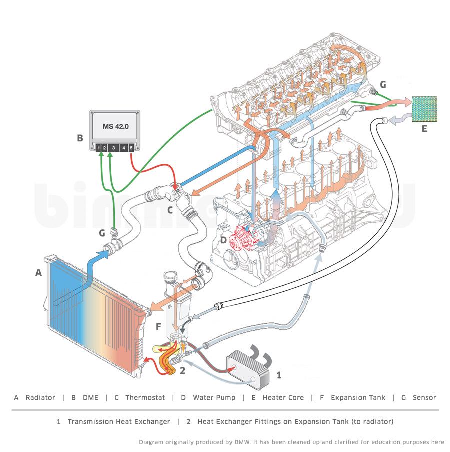
45 engine coolant flow diagram
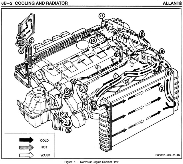
In this diagram you will see the rear cylinders ( #5 and #6 ) circled in red. If you follow the flow chart from the water pump you will see that coolant flows into the engine from that point, up through the heads and into the engine block. Coolant flows from the front of the head to the rear and exits through the water pipe connected to both sides. Northstar engine coolant flow diagram. Start by checking to see how much coolant is in your system. 3 4l Engine Coolant Diagram Top Engine Fuse Diagram Another issue is the check engine soon light appears and a green temperature light appears as well but the car temperature in the dash is where it should be even though the engine is hot.
I did spend a fair bit of time on these, so if they do happen to find their way elsewhere on the web, make sure at the very least to cite where they came from. Red = oil passages. Blue = water passages and flow direction. Yellow = direction of water flow in flexible hoses. 1970-1974 240Z / 260Z. 1975-1978 280Z.

Engine coolant flow diagram
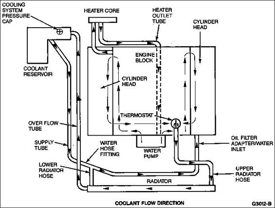
Hi, Does anyone have a diagram showing the flow of coolant around the engine / radiator etc. I have a 302 engine and the two small outlets on the water pump have been bridged - I assume these were for the heater matrix, and at the back of the heads there seems to be coolant ways which have been blocked off, I'm worried that this will over heat the heads if there is no flow! The cold water from the radiator comes into the engine at the head, where you want the coldest water to keep your valves from burning up. This is the standard cooling plan for every engine since the flathead V-8 was built by Henry Ford. Reversing this would flow would make your cooling system inefficient - but it would still work. Illustration of Automotive Cooling System infographic diagram showing process and all parts included radiator hoses coolant flow thermostat fan tank and air ...
Engine coolant flow diagram. AUTOMOBILE COOLING SYSTEM COMPONENTS flushing your cooling system has many benefits Besides preventing overheating and engine failure, periodic flushing allows components you don̵… orionsky234 O One would expect the coolant to NOT go through the radiator until the thermostat opens up and allows the coolant to flow through the radiator to lower the temp of the rising fluid due to engine heat. Someone else please clarify - if there is a diagram of the flow, that would be much appreciated for the 'young ones' on here.... Or you could put a pan under radiator to catch coolant spill, Put pan under radiator, remove radiator cap, start engine,let engine run,have a 50% coolant mix on hand, when engine warms up the thermostat will open and allow flow of coolant. just as the thermostat starts to open air will release causing coolant to spill over filler cap inlet ... Honda civic cooling system diagram. You can also find other images like wiring diagram parts diagram replacement parts electrical diagram repair manuals engine diagram engine scheme. Most important which way does the flow happen. So i was hoping to find a flow diagram for the cooling system on our d15bd16z6 setups.
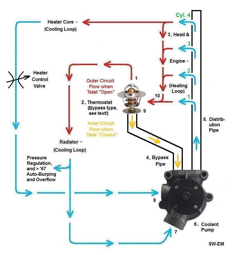
This is important to engine operating efficiency because it's not always the coolant temperature rather the coolant flow that determines if and when detonation occurs. Therefore an engine with maximum flowrate through the cylinder heads offers the best opportunity for achieving the maximum spark timing. Tags: closed cooling, flow diagrams The coolant flows in two circuits. When cold, it flows in a closed loop in the engine block for fast heatup. At that point, the radiator coolant is stagnant, more or less. When the coolant in the block heats up enough, the thermostat opens and flow to radiator circuit is added. They are not exclusive, just employed strategically, depending on temp. LSx engine have traditional coolant flow, block first, then the heads, and out. The LSx has both the in and out ports in the block, in is low (rectangular port) , out is top (round port), each bank of the engine is separate, merging/diverting in the water pump! GM LSx coolant flow path; Hope that helps, Paul. Edited July 30, 2009 by BRAAP Typos The return coolant flow is controlled by the thermostat located at the inlet (bottom hose) to the engine. This allows the thermostat to keep the water in the radiator moving faster or slower depending on the coolant temp. This inlet is also where the water pump is located. If you have a 4WD 5vz-fe, yer oil cooler circuit comes off of the water ...
About the connecting coolant hose from the hard line, view #8 on the coolant flow diagram; Honda PN #19503-PHM-000 HEATER PIPE, over to the water pump. Its the larger of the coolant hoses (not radiator hose) that is connected to the water pump. The factory replacement for this hose is PN #19509-PHM-000. Ls3 engine coolant flow diagram. 19354328 ls3 engine control system kit. 19329243 thank you for choosing chevrolet performance as your high performance source. The ls3 should be the same. Rev 16oc14 part no. Mass air flow sensor and engines throttle body. Lsx engine have traditional coolant flow block first then the heads and out. The engine ... N52 Coolant Flow Diagram Attached is an example of a Coolant Flow Diagram. This is a screenprint from BMW Training Manual ST501 Engine Technology, Part 04 Engine Mechanical, page 33. It is for the N54 engine. What I am asking for is ANY cite or link to a similar Flow Diagram for the N52 engine. Cooling System Flow. Dodge L Cummins Cooling Kit Improves Coolant Flow to Cylinder #6. Install the rear plate (8) marked & o ring (9) in the diagram, then using heater. L Engine and Transmissions () Archive > This would allow the heater to run with the same water flow as if the engine I searched all over the internet for coolant flow diagrams ...

Does anyone have a diagram for the coolant flow direction on a 1990 5.0 EFI HO ?
The volumetric flow of the coolant pump V pump for the engine speed equal to 3000 rpm was assumed to be equal 0.00037 m3/s, similarly as in [64], the coolant pump head is equal 67 m and the ...
Coolant Flow and Head Gasket Design. Most V-type engines use cylinder heads that are interchangeable side to side, but not all engines. Therefore, based on the design of the cooling system and flow through the engine, it is very important to double check that the cylinder head is matched to the block and that the head gasket is installed correctly (end for end) so that all of the cooling ...
Coolant Flow Radiator And Engine Block Below is an explanation of this system's operation The Thermostat Just like your body needs to warm up when you begin to exercise, your car's engine needs to warm up when it starts its exercise. The thermostat provides control for your engine's warm-up period.
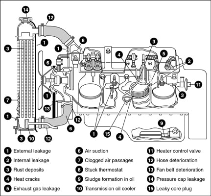
04-15-13 08:16 PM - Post# 2336040. In response to HMAJNG. Most all cooling systems with this much rust/water slurry circulating through the system will still continue to release rust particles and in a few weeks the coolant will be red again. Remember the slurry is abrasive to the tubes and solder in the radiator; and it soon may leak.

the direction of coolant flow is not . all coolant flow paths roughly equal in the crappy diagram below the blue.May 30, · Reverse flow cooling is THE KEY to the Generation II LT1s increased power, durability, and reliability over the first generation smallblock engine. There are three main circulation systems for the LT1, while most engines ...

Northstar Engine Coolant Flow Diagram. How to Flush the Cooling System on a Northstar Engine. Whether your vehicle's cooling system is having problems or not, annual flushing is very important to prevent future problems like corrosion of the internal parts which can cause head gasket failure as early as 60,000 miles.

Nov 5, 2009 — The flow of coolant will either be stopped at the thermostat until the engine is warmed, or it will flow through the thermostat and into the ...
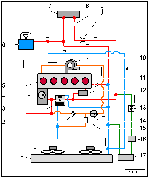
If there are customer complaints about poor heat output of the air conditioning system when the auxiliary heater is switched off (with engine running and/or at standstill, irrespective of whether -Z115- is activated or not), make sure the coolant changeover valve 2 is installed with correct orientation and that it works properly → Current flow diagrams, Electrical fault finding and Fitting ...
Lt1 reverse flow cooling system diagram Conventional cooling systems have passages in the intake manifold which allow coolant to crossover from one side of the engine to the other. In the LT1, coolant crossover occurs in the water pump, which is also where the thermostat is located.
Ford mustang cooling system diagram. flow diagram. Here is the DOHC cooling flow diagram. The heater is in series with the cooling system so you should use a four port heater control valve. I will post some photos when I get things put back together. Breeze has a very nice lower coolant pipe option for the 4.6 DOHC w/ FFR radiator. -Mark.

Dec 12, 2008 — I have done a few 240Z LS swaps. I get the parts from Johns Cars. Same company as Jags that run. Good fitment and super affordable If you ...15 posts · I've been looking, I have a Haynes but there's no such diagram in it. Can anyone point me ...

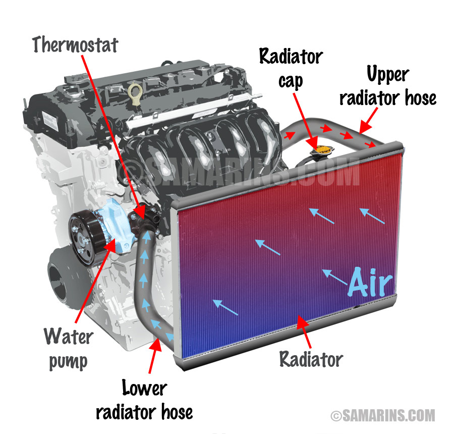
Engine Fan Test — The cooling system is made up of: passages inside the engine block and heads; a water pump to circulate the coolant; a thermostat to ...
Cooling system 29 30 Cooling System Flow: EGR Coolers • Cooled coolant flows out of the supply port of the front cover where it is routed to the horizontal cooler at the left rear side of the engine. • The coolant then exits the horizontal cooler and is immediately routed into the vertical cooler. The coolant
7.3 Powerstroke Coolant Flow Diagram. How to flush the engine coolant in a L Power Stroke and perform a complete cooling system service, including upper radiator hose, lower radiator hose, and. Maintaining the coolant system is just as important as an oil change — in fact, the coolant condition in a diesel engine may even be more.

Illustration of Automotive Cooling System infographic diagram showing process and all parts included radiator hoses coolant flow thermostat fan tank and air ...
The cold water from the radiator comes into the engine at the head, where you want the coldest water to keep your valves from burning up. This is the standard cooling plan for every engine since the flathead V-8 was built by Henry Ford. Reversing this would flow would make your cooling system inefficient - but it would still work.

Hi, Does anyone have a diagram showing the flow of coolant around the engine / radiator etc. I have a 302 engine and the two small outlets on the water pump have been bridged - I assume these were for the heater matrix, and at the back of the heads there seems to be coolant ways which have been blocked off, I'm worried that this will over heat the heads if there is no flow!


0 Response to "45 engine coolant flow diagram"
Post a Comment