41 utv turn signal wiring diagram
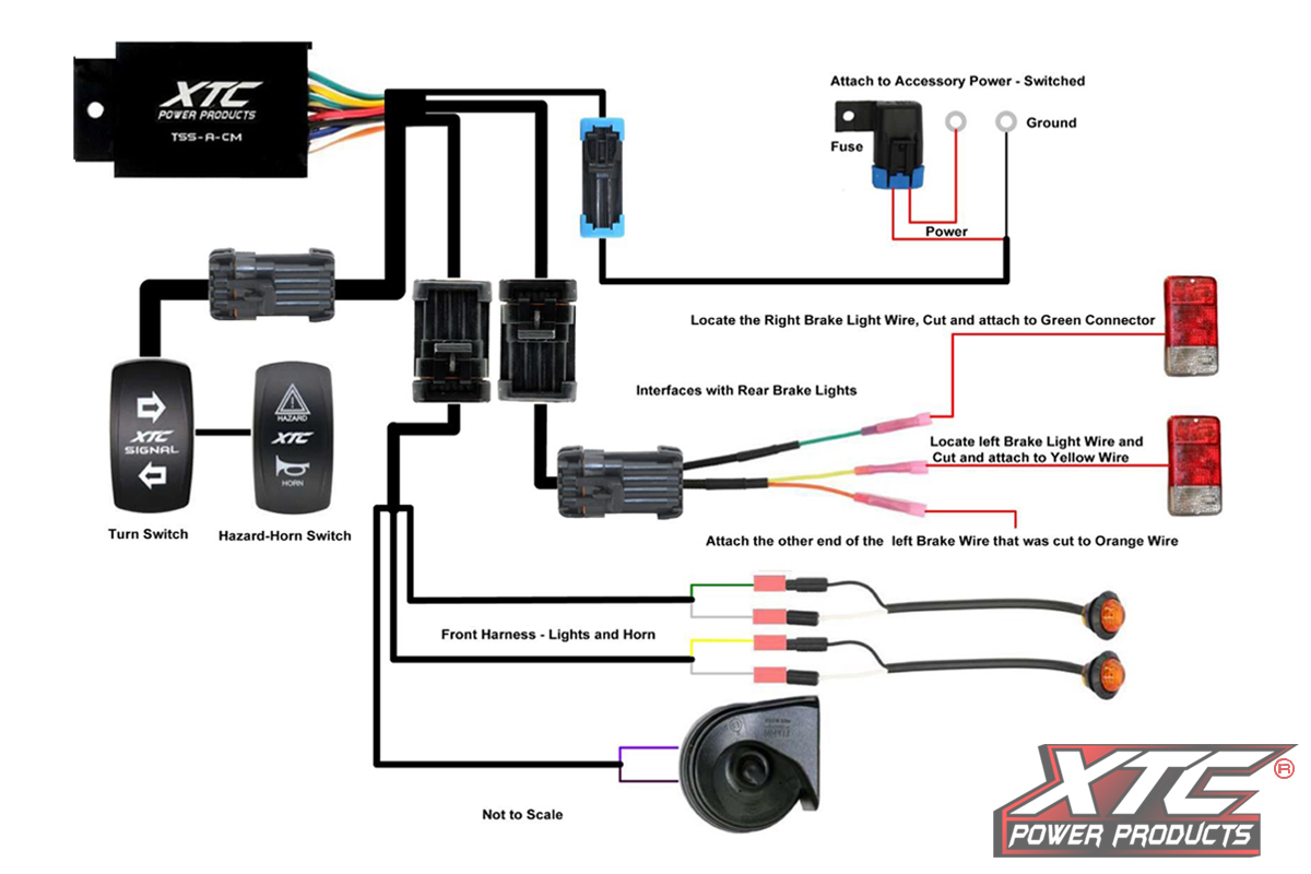
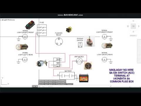
Turn Signal Light (driver) Turn Signal Light Turn Signal Light: - Drill a Ø3/4" hole in body and install Turn Light. Repeat for remaining Turn Signal Lights. - BLACK wire is positive and WHITE wire is ground. - WHITE wires on Wiring Harness are grounds, GREEN wire is right turn, and YELLOW wire is left turn. Mcs Utv Vehicle Safety Switch Turn Signal Kit With Horn And Hardware 2 Amber Red Round Leds License Plate Led Atv Kits. Do it yourself utv atv turn signals how to add and wire them up universal plug play signal kit lgt 132b assy wiring diagram self canceling install a on your for dummies brake hazard lights chrome switch 8 detailed tusk horn switches inc find diy flasher relay kits led toggle ...
If you choose the toggle switch type, then the Toggle Switches LED Turn Signal Kit #604 will be your choice. We hope this helped you in choosing a turn signal kit for your UTV (side-by-side). On the other hand if not, please call us at (623) 435-1337 and we will be happy to answer any and all questions.

Utv turn signal wiring diagram
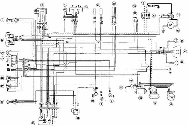
yamoto 70cc wiring diagram posted below atvconnection atv rh atvconnection. We collect plenty of pictures about Atv Turn Signal Wiring Diagram. and finally we upload it on our website. Many good image inspirations on our internet are the best image selection for Atv Turn Signal Wiring Diagram. . Universal Turn Signal Switch Wiring Diagram - empi universal turn signal switch wiring diagram, grote universal turn signal switch wiring diagram, universal motorcycle turn signal switch wiring diagram, Every electrical arrangement is composed of various different components. Each component should be set and connected with other parts in specific way. I want to install my own turn signals that I purchased (aftermarket) (cause I am not paying $1500 for turn signals). Anyhow I have been trying to figure out where I can purchase a connector for the Power wire under the hood for the CFMoto turn signals. All I want is the connector and not change the wiring, nor do I want to splice into the wiring.
Utv turn signal wiring diagram. FULL SIZE UTV UNIVERSAL TURN SIGNAL / HORN KIT (15950) Female Spade Connectors Turn Signal Detail 800-643-7332 Procedure: 1 15767 ... Turn Signal Switch Red, Green & Yellow wires from harness ... Wiring Diagram Front Left Signal I added numerous upgrades to my 2020 RZR XP4 1K. Below is the explanation of it all and then I included the wiring diagram (I know it's not the best, but it's what I could come up with). XPRITE LED Chase Lightbar : This is wired for multiple functions. This bar is wired into the taillights for the stop activation, the turn signal kit for that ... Your Wiring Leader in Plug and Play Turn Signal Kits, Switch Systems, Rocker Switches and 12v Power for Polaris, Can-Am, Honda, Roxor, Yamaha & Kawasaki UTV. UTV Turn Signal Kit, kemimoto Universal Turn Signal With Column Turn Switch & 105D Horn With Button Amber LED Blinker Kit Wide Compatible With Polaris, Pioneer, Can-Am, Kawasaki, Arctic Cat. 3.5 out of 5 stars. 14. $159.95.
Top 6 Turn Signal Systems for Side-by-Side UTVs. The turn signal system you buy for your side-by-side depends on the type of UTV you have. Each manufacturer has its wiring layouts and purchasing the wrong kind of system could be a headache. While there are universal models, many companies specialize in only one type of vehicle. Wiring Diagram Intimidator Utv Turn Signal. REVIEW THE WIRING DIAGRAM ON PAGE 4. 2. Locate and Turn Signal Switch and the LED Turn Signal Indicators. protect the finish of the UTV's Dash. 2. Results 1 - 48 of Mahindra Mpac or Intimidator Full Tilting UTV Windshield (Fits: . 12v HORN for SXS UTV + Turn Signal Kit Wiring Diagram for DIY All. Manual. Chevy Turn Signal Relay Wiring Diagram - Wiring Diagram Data Oreo - Turn Signal Flasher Wiring Diagram. Wiring Diagram arrives with numerous easy to stick to Wiring Diagram Guidelines. It is intended to aid each of the average person in developing a correct program. These instructions will likely be easy to comprehend and use. Turn Signal wiring diagrams Recently I asked on FordBarn if anyone had wiring diagrams for the particular turn signal system (Everlasting) that I have mounted on my '29 Tudor . I had many responses and have collected them in the pages that follow. Unfortunately I didn't retain the sources. :-(In addition, I browsed the 'net and found a few more.
Drill the marks for the turn signal indicator lights out with a 5/16″ drill bit. Remove the nut from the back of one of the turn signal indicator lights. Install the light into the hole, feeding the wires through first. Finger-tighten the nut on the backside of the light. Repeat these steps for the other turn signal indicator light. Utv Turn Signal Wiring Diagram. Print the wiring diagram off plus use highlighters to trace the signal. When you make use of your finger or perhaps the actual circuit with your eyes, it is easy to mistrace the circuit. 1 trick that We 2 to printing a similar wiring plan off twice. Upon one, I'll trace the current movement, how it operates ... Turn Signal Flasher Wiring Diagram - led turn signal flasher wiring diagram, motorcycle turn signal flasher wiring diagram, turn signal flasher circuit diagram, Every electric arrangement consists of various unique parts. Each part should be placed and linked to other parts in specific way. If not, the structure won't work as it ought to be. Like. Comment & Subcribe :)'DO IT AT YOUR OWN RISK'Follow me onFacebook: MotoFix PHSEND ME STUFF?FOR SPONSORSHIP?Business inquiries!Email me: motofixph@gmail...

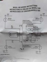
turn signal switch with integral pilot lamps ... wiring left diagram . righr rear right rear 11]rn- lefr rear rurn- left sronruu lefr right front ruu-red - 'hi re 'ire srrlpe diagram her brake stripe headlighr - white left front turn-green typical wiring . continuity diagram 3456 7 8 9 functions headl dimmer 2 stop rn turn turn turn ight rear ...

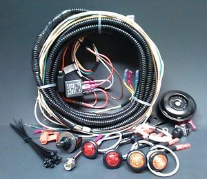
Tusk UTV Horn & Signal Kit Installation Instructions The Tusk UTV signal kit is designed to be a simple way to provide front and rear turn signals, license plate mount with light, horn, and rearview mirrors for your machine. This kit has universal applications and will work on almost any side-by-side.

Wiring Diagram Intimidator Utv Turn Signal So, I sat down and drew out a simple diagram for turn signals and on the UTV, since I really didn't want to interrupt the existing wiring and. Results 49 - 96 of Mahindra Mpac/Intimidator 20" HALF WINDSHIELD (Fits: 12v HORN for SXS UTV + Turn Signal Kit Wiring Diagram for DIY All.

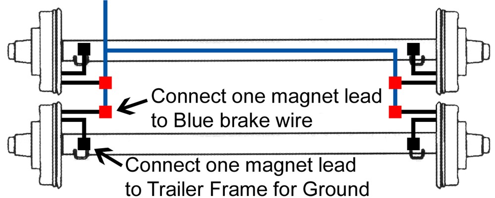
vehicle ignition wire. Locate the red wire on the turn signal relay harness, it is the wire that contains the in-line fuse holder. Insert the end of the red wire into the tap, then fold the cover over and press together. 23 Identify the Referencing the wiring diagram at the right, ORANGEwire on the Turn Signal Relay Harness.

I just bought a 2017 XP1000 as well, I like your ideas. I agree we need a diagram to understand how your turn signals are actuated. May be able to use diodes or relays to keep the brake lights from backfeeding but you really need an oem style turn signal type switch to open the brake ckt to either side when the turn signal is active.

REVIEW THE WIRING DIAGRAM ON PAGE 4 2. Locate and disconnect the battery. 3. Determine where on the paneling near the Front and Rear light casing you will be installing the LED Turn Signal Lights 4. Determine where on the Dash you are going to mount the Turn Signal Switch and the LED Turn Signal Indicators.
American Autowire Universal and Classic Update Kit Bolt On Turn Signal Switch wiring instructions.(updated)
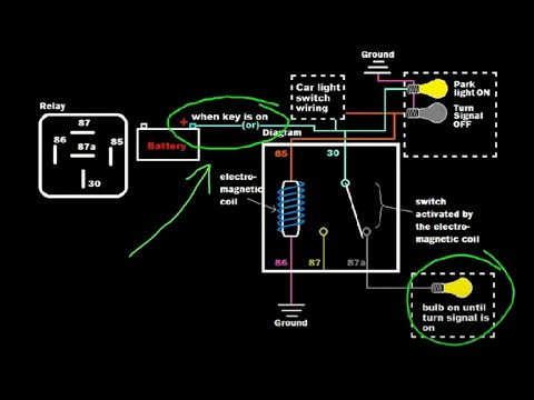
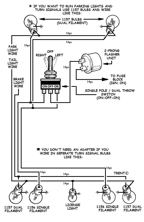
The Wiring. Let's take a look at how the turn-signal circuit is hooked up. The turn-signal circuit gets power when the ignition key is on. The power goes through a fuse panel into the thermal flasher. From there it goes to the stalk on the steering column. Depending on the position of the turn-signal stalk, the power either stops in the switch ...
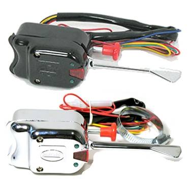
The Dux Deluxe Signal kit is well made, with a high-quality, color-coded wiring harness and turn-signal switch with horn button and emergency flashers. Everything needed for installation is in the kit, except for the tools (e.g., drill, 3/4-inch and 7/16-inch drill bits, electrical pliers/crimper, diagonal cutters, Torx and screwdrivers, etc).
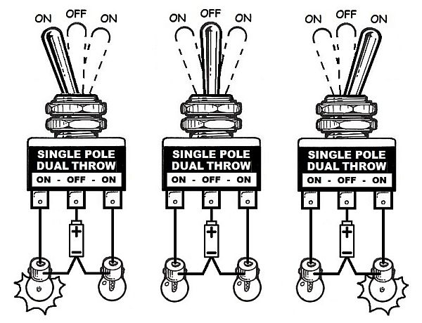
1. Use a factory switch. 2. Use an aftermarket switch. 3. Make your own switch system. (It's easy!) Factory switch Most of you will have a hotrod that uses a steering column that has a turn signal switch built in. What you need to do is find the wiring diagram for the vehicle the column came from.
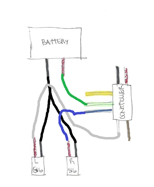
So, I sat down and drew out a simple diagram for turn signals and emergency flashers using components readily available from Amazon or other similar sources. Simple, home-made brackets secure the front turn signals to the UTV cage, and the internet LED turn signals have rubber dampers for long life. Rear signals mount to the shoulder belt mounts.
I want to install my own turn signals that I purchased (aftermarket) (cause I am not paying $1500 for turn signals). Anyhow I have been trying to figure out where I can purchase a connector for the Power wire under the hood for the CFMoto turn signals. All I want is the connector and not change the wiring, nor do I want to splice into the wiring.

Universal Turn Signal Switch Wiring Diagram - empi universal turn signal switch wiring diagram, grote universal turn signal switch wiring diagram, universal motorcycle turn signal switch wiring diagram, Every electrical arrangement is composed of various different components. Each component should be set and connected with other parts in specific way.

yamoto 70cc wiring diagram posted below atvconnection atv rh atvconnection. We collect plenty of pictures about Atv Turn Signal Wiring Diagram. and finally we upload it on our website. Many good image inspirations on our internet are the best image selection for Atv Turn Signal Wiring Diagram. .


0 Response to "41 utv turn signal wiring diagram"
Post a Comment