41 diverging lens ray diagram
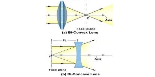
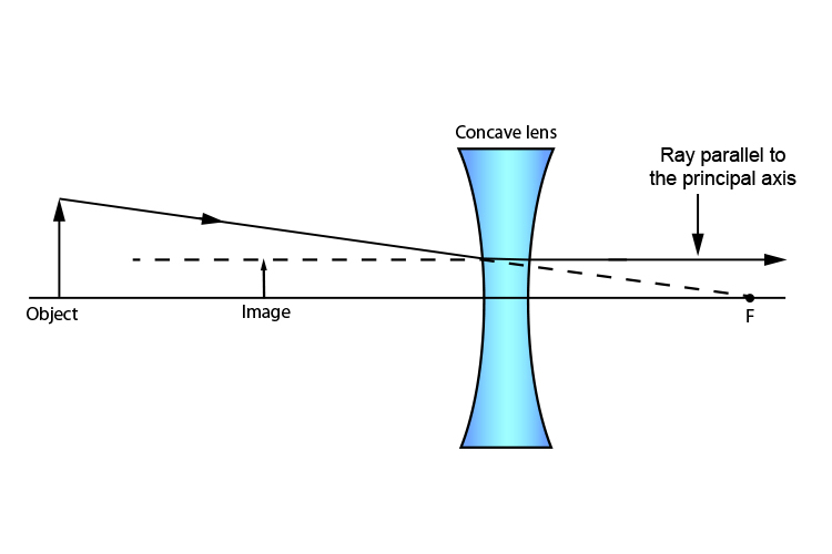
For a Concave lens,There are only 2 casesThey areObject is Placed at InfinityObject is Placed between Infinity and Optical CenterCase 1 - Object is Placed at infinityIn this Case, Object is kept far away from mirror (almost at infinite distance)So, we draw rays parallel to principal axisSince ray pa
setups. Students will then be formally taught lens diagram terminology as well as the ray diagram laws of refraction. With this formal knowledge, students will recreate both the convex and concave lens setups followed up by a separate lens setup to represent the anatomy/physiology of the human eye. Materials: (for groups of 2-3 students)
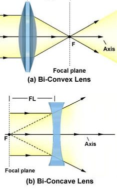
When drawing ray diagrams for lenses, there are a few more important things to note. Firstly, lenses can either be drawn as lens shapes or as lines with arrows on them. The convention is that a diverging lens has inwards pointing arrows and a converging lens has outwards pointing arrows, mimicking the shapes of the lenses.
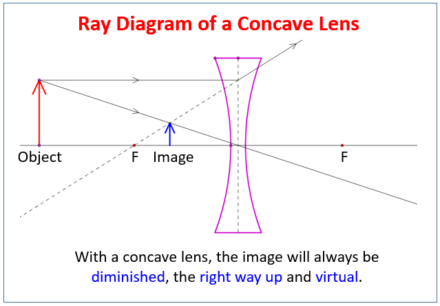
Diverging lens ray diagram
Ray Diagrams By constructing a ray diagram, we can determine where the image is located, and what it will look like. A ray diagram is a diagram showing rays that can be drawn to determine the size and location of an image formed by a mirror or lens.
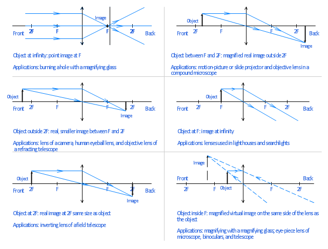
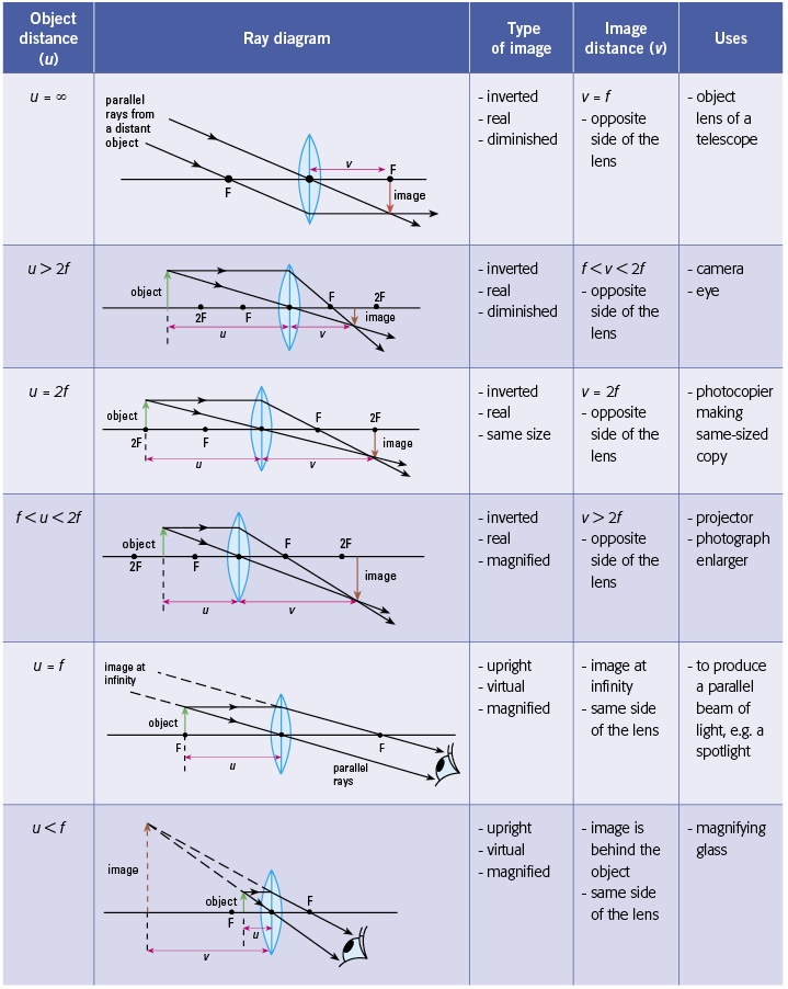
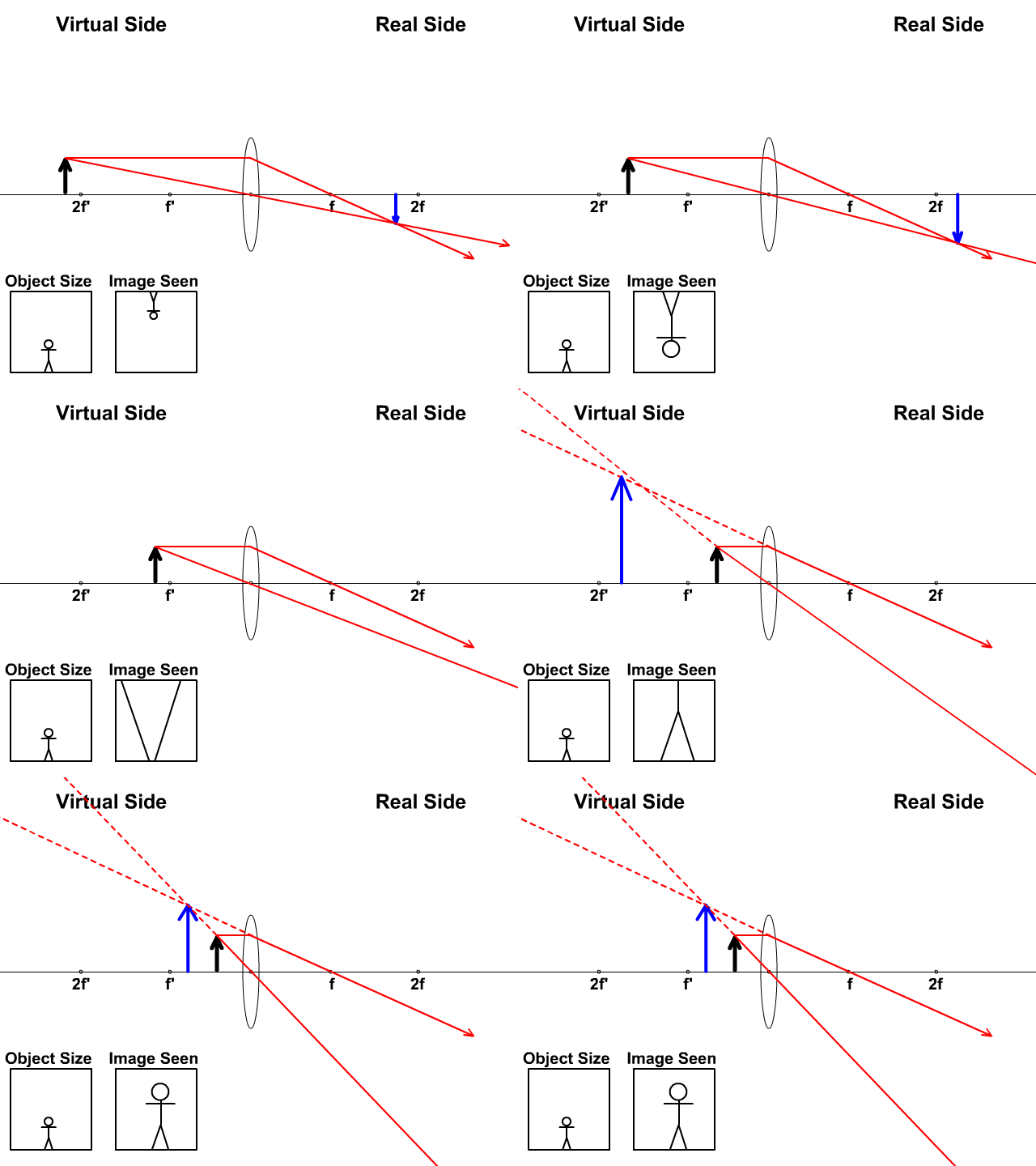
For a Convex Lens, object can be kept at different positionsHence, we take different casesCase 1 - Object is Placed at infinityIn this Case, Object is kept far away from lens (almost at infinite distance)So, we draw rays parallel to principal axisSince ray parallel to principal axis passes through t
To explain how to draw the diagrams, there are two key things to remember. 1 A converging lens refracts the light so that any ray of light parallel to the principal axis (the thick horizontal line) is turned to pass through the focal point. Rays of light parallel to the principal axis are all refracted through the focal point.
Diverging lens ray diagram.
Two Converging Lens Ray Diagram. Examples are given for converging and diverging lenses and for the cases where the The third ray is not really needed, since the first two locate the image. In this section of Lesson 5, we will investigate the method for drawing ray diagrams for objects placed at various locations in front of a double convex lens.
A convex lens is thicker in the middle than it is at the edges. Parallel light rays that enter the lens converge. They come together at a point called the principal focus. In a ray diagram, a ...
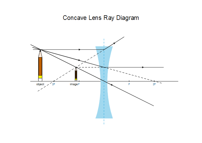
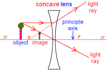
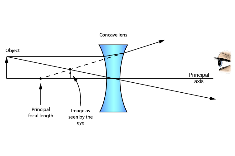
Here you have the ray diagram s used to find the image position for a diverging lens.A diverging lens always form an upright virtual image. Ray diagram s are constructed by taking the path of two distinct ray s from a single point on the object: A ray passing through the center of the lens will be undeflected. A ray proceeding parallel to the principal axis will diverge as if he came from the ...
The focal length of the of a diverging lens is 4 cm, the distance of the object from the lens is 8cm and the height of the object is 4 cm. Question: Use Ray Tracing Diagram to locate the position and height of the image by a diverging lens. The focal length of the of a diverging lens is 4 cm, the distance of the object from the lens is 8cm and ...
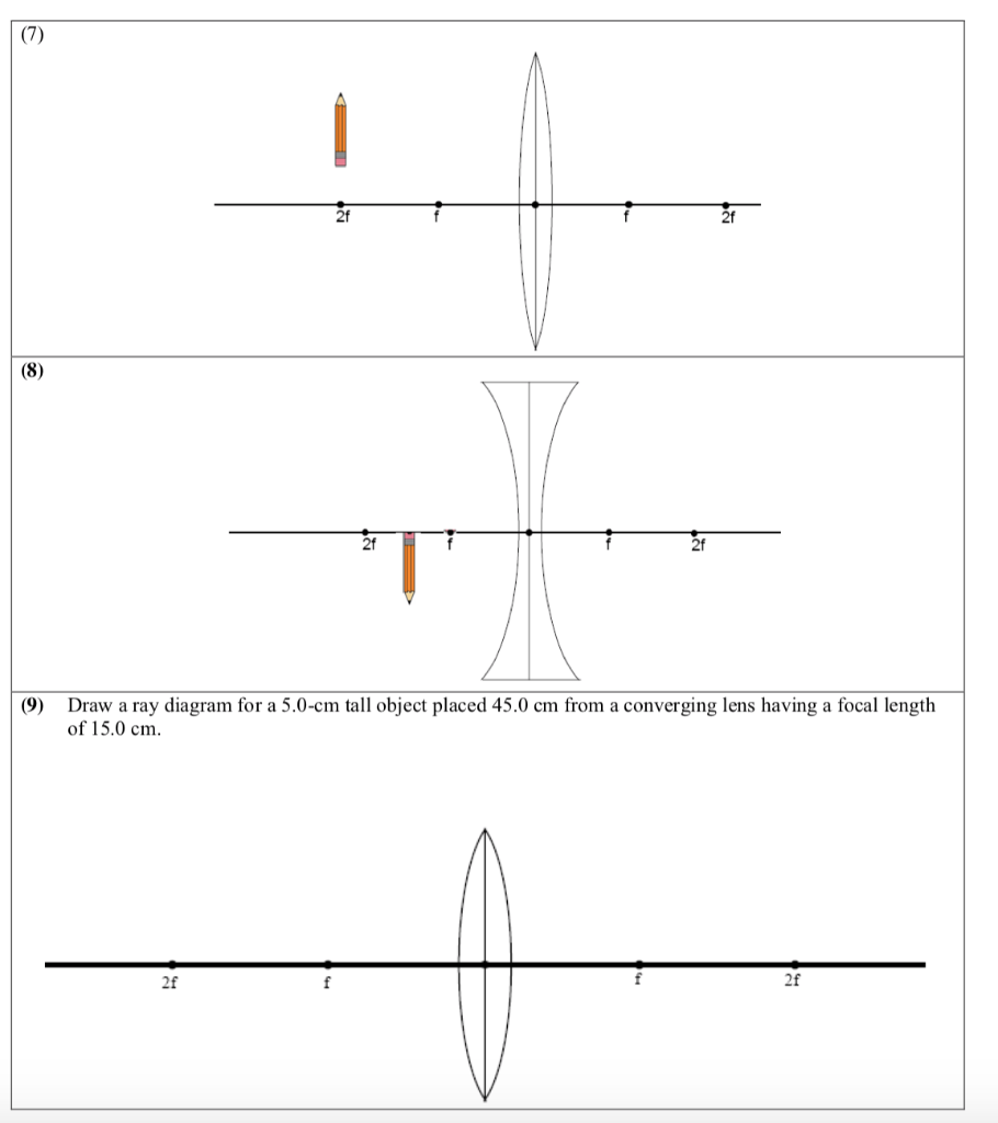
In this lab, you will construct the TWO ray diagrams for diverging lenses. In each diagram, use an arrow, 2.0 cm tall, pointing upwards as the object. Label it with an O. For your convenience, blank diagrams will objects already provided are located on this page -- in IE use landscape mode with margins of 0.5.
Description of how to draw ray diagrams for diverging lenses for grade 10 science.
A tutorial on how to draw ray diagrams for a diverging lens.
Ray 1 is parallel to the axis and refracts as if from F. Ray 2 heads towards F' before refracting parallel to the axis. Ray 3 passes straight through the center of the lens. image is always virtual, upright and reduced O F I F' Ray diagram for diverging lens
Real images occur when objects are placed outside the focal length of a converging lens (s>f). If the lens is converging but the distance from the object to the lens is smaller than the focal length, the image will be virtual. Diverging lenses always produce virtual images. This calculator shows a ray diagram when the image is real. Magnification
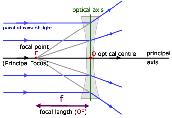
The ray diagram constructed earlier for a diverging lens revealed that the image of the object was virtual, upright, reduced in size and located on the same side. Any incident ray traveling parallel to the principal axis of a diverging lens will refract through the lens and travel in line with the focal point (i.e., in a direction such.
View Notes - Diverging Lenses - Ray Diagrams from GEO 111 at Vilniaus Gedimino technikos universitetas. 3/6/2011 Diverging Lenses - Ray Diagrams h om e - a bout - te rm s - cre dits - fe e dback T
Ray Diagram for Object Located in Front of the Focal Point. In the three cases described above - the case of the object being located beyond 2F, the case of the object being located at 2F, and the case of the object being located between 2F and F - light rays are converging to a point after refracting through the lens. In such cases, a real image is formed.
This Demonstration lets you visualize the ray diagrams for converging and diverging lenses. By manipulating the object and lens locations, you can create real or virtual images. The rays parallel to the principal axis and the ray through the center of the lens are drawn.Locators allow you to drag both the object and the lens. You can change the focal length using a slider.
(10) Draw a ray diagram for a 3.0-cm tall object placed 10.0 cm from a converging lens having a focal length of 15.0 cm. (11) Draw a ray diagram for a diverging lens that has a focal length of -10.8 cm when an object is placed 32.4 cm from the lens's surface. (12) Draw a ray diagram for an object placed 6.0 cm from the surface of a converging lens with a focal length
Diverging lens. Author: Ray Tuck. This simulation shows a ray diagram for a diverging lens. Use the slider to set the position of the object. The object is shown by a black arrow. Use the check boxes to choose which rays to show. You need any two to fix the position of the image. The image is shown by the red arrow.
Ray diagrams for diverging (concave) lens. If an object is on one side of the concave lens, the concave lens can form the image of the object. If the position of the object on one side of the concave lens is known, how to draw the image formation of the object? Suppose an object is on the left side of the concave lens as shown in the figure below.
[Watch this document for the addition of more diagrams and expanded ... A diverging lens causes exiting rays to be more divergent coming out than thay were ...
14+ Diverging Lens Ray Diagram. Examples are given for converging and diverging lenses and for the cases where the object is inside and outside the principal focal length. Ray tracing for concave or diverging lens draw different ray diagrams with the object at different places in relation to the focus and find out where the image appears.
A real image is formed by a converging lens. If a weak diverging lens is placed between the converging lens and the image, where is the new image ...15 pages
A diverging lens ray diagram follows three basic rules: Any ray of light that is parallel to the principal axis of the lens will pass through its focal point after refraction. Any incident ray of light that passes through the focus of the lens before getting refracted will emerge parallel to the principal axis on refraction.
Diverging Lenses As such, the rules for how light behaves when going through a diverging lens is a little bit different. You will be expected to be able to draw a Ray Diagram of a converging and diverging lens on our upcoming test without the rules.
The ray diagram constructed earlier for a diverging lens revealed that the image of the object was virtual, upright, reduced in size and located on the same side. Any incident ray traveling parallel to the principal axis of a diverging lens will refract through the lens and travel in line with the focal point (i.e., in a direction such.
Here you have the ray diagrams used to find the image position for a diverging lens. A diverging lens always form an upright virtual image. Ray diagrams are constructed by taking the path of two distinct rays from a single point on the object: A ray passing through the center of the lens will be undeflected. A ray proceeding parallel to the principal axis will diverge as if he came from the ...
Ray Diagrams for Lenses. The image formed by a single lens can be located and sized with three principal rays. Examples are given for converging and diverging lenses and for the cases where the object is inside and outside the principal focal length.
Earlier in Lesson 5, we learned how light is refracted by double concave lens in a manner that a virtual image is formed.We also learned about three simple rules of refraction for double concave lenses: . Any incident ray traveling parallel to the principal axis of a diverging lens will refract through the lens and travel in line with the focal point (i.e., in a direction such that its ...












0 Response to "41 diverging lens ray diagram"
Post a Comment