40 hydraulic spool valve diagram
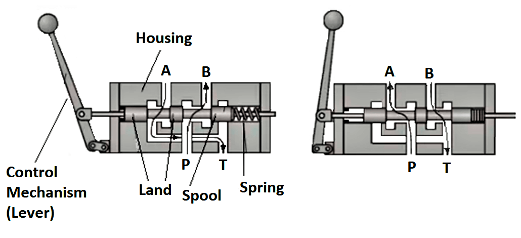
While shopping online, select "Contactless Curbside Pickup In Store" for eligible items. Select the store where you would like to pick up your items. Place your order and wait to receive a "Ready For Customer Pickup" e-mail. This is a separate e-mail from your order confirmation and is the notification that the order is actually ready for pick ... This valve below has a solenoid on one end and a spring on the opposite end. Now we are going to insert the spool into the body. This is an Eaton-Vickers #2 Spool. By combining the two Pictures, we get a full valve operation. Combined valve operation. Shown here, the valve is in its non-energized position. The Spring is in control.
Interesting ingenuity n175h. Keep in mind though, that brass ball valve is not rated for hydraulic pressure and can burst. One thing you could do to prevent bucket drift down caused by faulty control valve would be install either a pilot operated check valve or pilot operated counterbalance valve at cylinder lines.

Hydraulic spool valve diagram
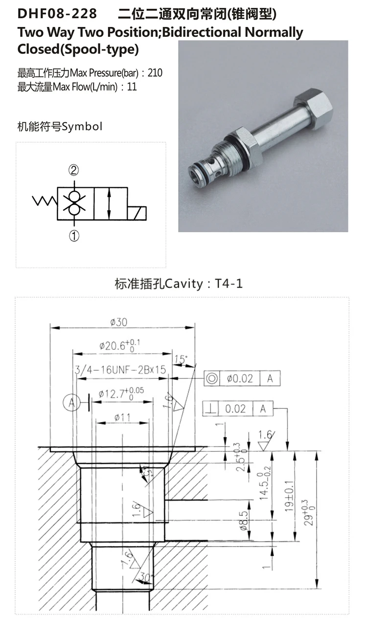
The phantom leak is fixed! Finally!Thank you to Jake Zeigler and CE Smith for the helpProduced with CyberLink PowerDirector 12 Spool Valve Cover Ford 10 40 60 TS TW - PACK OF 2 - PRICE PER UNIT. Spool Valve Cover Ford 10's 40's 60's TS TW. Code: 41919. Loading... Spool Valve Cable. Spool Valve Cable Ford 60 Series TM - Cranked Lever. Spool Valve Cable Ford 60 Series TM. Code: 42037. Loading... Hydraulic Spool Valve Diagram Introduction: E -Type Features: In the neutral position , all oil ports closed, not flow . Functional characteristics: 1. The inlet and outlet ports of device are closed, hydraulic actuator can be fixed in any its' working mechanism position, and no movement or rotary further even if there is external force on it ...
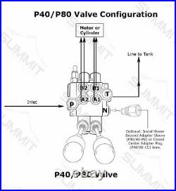
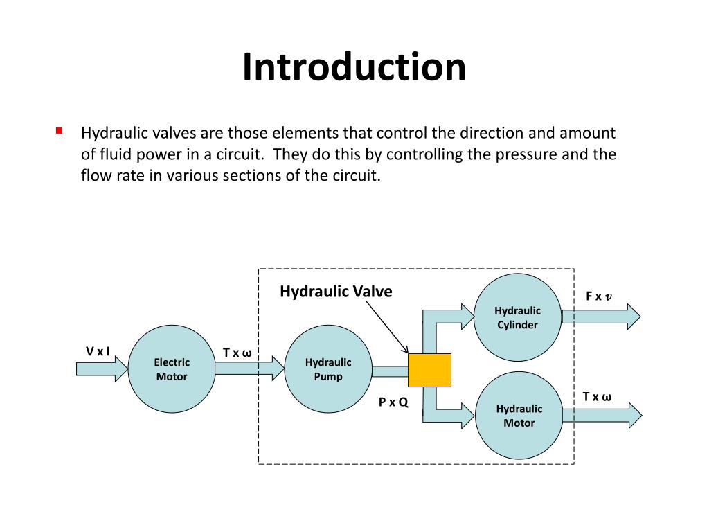
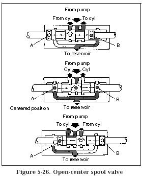
Hydraulic spool valve diagram. a hydraulic valve. 2 of 6 3 of 6 4 way 3 position tandem center Powers cylinder or motor in both directions (metering capability is very limited). Pump unloads to tank when spool is in neutral. cylinder or motor blocked when spool in neutral 3 position spring center to neutral Pressure (PSI) Pressure drop P A(B) on 6 sections dDIRECTIONAL valve Spool detent - detent with hydraulic release (70 to 140 bar) Spool type (A) Directional control valve (80 l/min) Order Code: P81 A 2 G 12 117,5 8,4-3x 85 46,5 36 P T 200 64 75 10 29 B A Availabe threads for that valve: UN-UNF (order code S10) Working ports A, B: 7/8-14UNF Inlet port P: 1-1/16-12UNF Outlet port T: 1-1/16-12UNF hydraulic control valve. The valve shown in the illustration is a open center valve, meaning that the oil flow is returned to the reservoir when the valve is in the neutral position. The spool valve has the capability to direct fluid flow to either end of the actuator. As the spool is moved, fluid is redirected to one end or the other of the Hydraulic Four-Way Valves. Four-way, directional-control valves are used to control the direction of fluid flow in a hydraulic circuit, which controls the direction of movement of a work cylinder or the rotation of a fluid motor. These valves are usually the sliding-spool type. A typical four-way, directional-control valve has four ports:
hydraulic test pom plugged port rotary union detent return above'below fluid level check valve shut-off valve spool controls energy transformations ... directional valve (spool form 2 (cc. 5evp3d2...) pilot operated solenoid fluid treatment breather with filter filter (eg. 2fa..,) filter with indicator procedure to assure the valve spool does not lock or bind as a result of the tightening. IF THE VALVE SPOOL BINDS IN ANY WAY OR REFUSES TO RETURN TO NEUTRAL WITH THE SPRING WHEN THE LEVER IS RELEASED, DISCONTINUE USE AND CALL FACTORY. 4. Since the kick-out operates from hydraulic pressure, the valve may not kick out when the oil is cold. Because the valve core and valve sleeve have a lubricating film of hydraulic oil, the friction factor is very small, and the spool mass is very small (2.547g), therefore, positive pressure between the spool valve and valve sleeve caused by the two accelerations is also very small; friction resistance change caused by it can be neglected, and ... Valve spool leak from Hydraulic control valve. Removal, Repaired, Reinstalled.
Symbols show: - The methods of actuation. - The number of positions. - The flow paths. - The number of ports a valve has. When we see a spool valve schematic, we can see it is made up of boxes, each containing a number of lines and arrows. The number of boxes that make up a valve symbol indicates the number of possible positions the ... Hydraulic Kick-out Adjustment - The SH & SHA models have an adjustable single hydraulic kick out preset to 800-1000 psi. The HHA model comes equipped with a double hydraulic kick out preset to 800-1000 psi. To adjust kick-out pressure: Locate jam nut, and set screw on the spool action cap. (Opposite valve's handle) 20-50-K4 08650015 V20 D/A Motor Spool. FOR SINGLE ACTING FLOAT USE 20-50-03 AND K-20-R. V20 SPOOL ACTION KITS. K-20-D 08650105 V20 Detent Kit (3 Position) K-20-R 08650106 V20 Spool In Detent (S/A Float) K-20-PA1 08650630 Air Shift. K-20-VH-B 08650151 Handle Kit Complete. V20 NPT Pipe Thread. 22 A schematic diagram of the David Brown Selectamatic Hydraulic System. Also a guide to repairs and some other useful tips. The DBTC are indebted to Mr. Alan Kellett who was a Product Training Instructor at the Meltham Hall Training School and Mr. Karl-Olof Kulberg (Ollek) who was Service Manager for DB, Case/IH from 1972-1999 in Finland who between them and with encouragement from Mr. Peter ...
Winch. The diagram shows a winch powered by a hydraulic motor. The directional control valve with built-in relief features optional flow control to control the speed of the winch . The hydraulic pump and motor must be matched to the torque requirements of the winch.

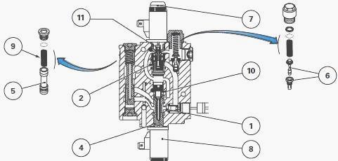
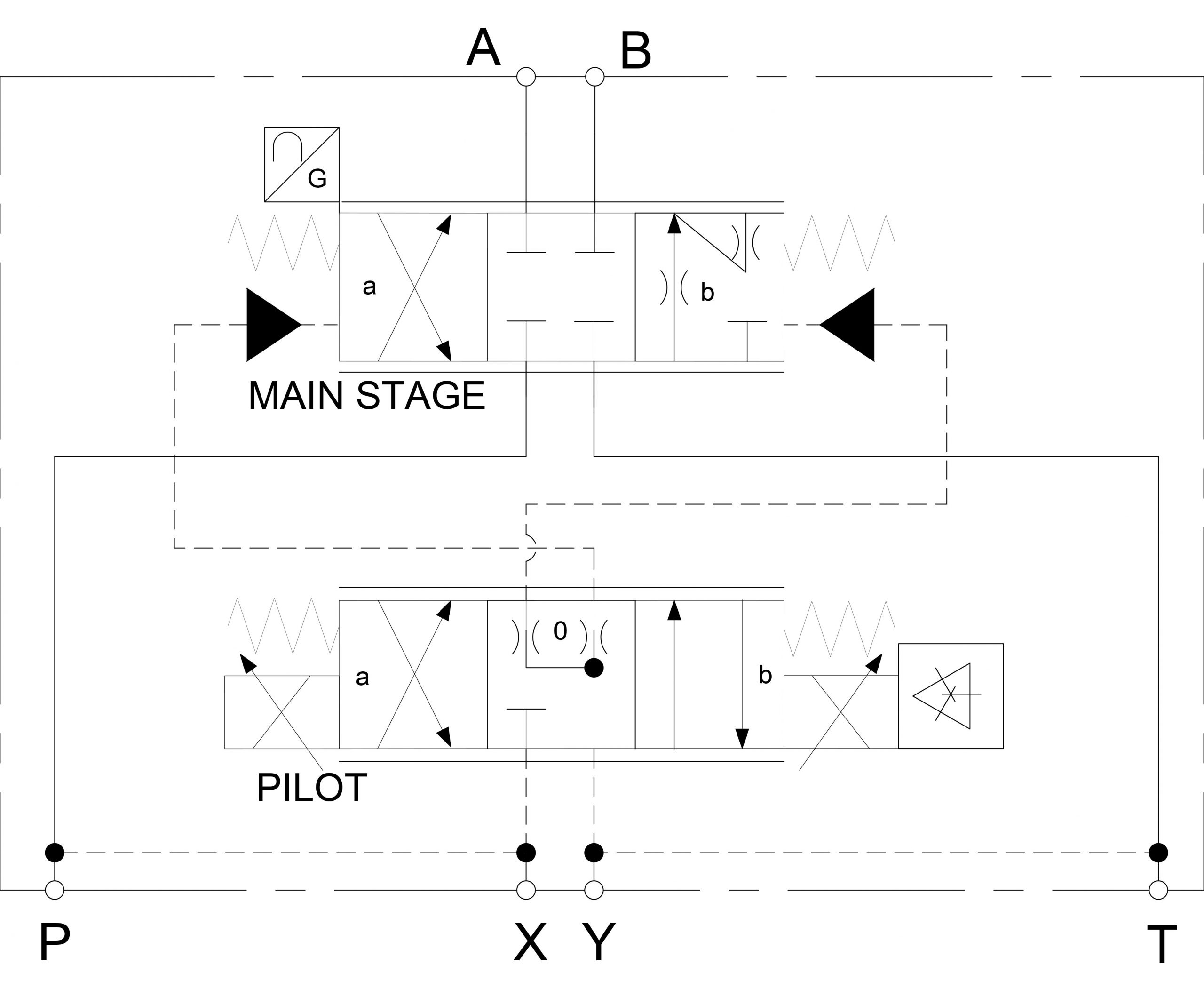
A hydraulic 4/2 pilot-operated spool valve is shown in Figure 4.18. The ends of the pilot spool in most hydraulic pilot-operated valves are visible from outside the valve. This is useful from a maintenance viewpoint as it allows the operation of a valve to be checked. In extreme cases the valve can be checked by pushing the pilot spool directly ...
Hydraulic spool valve operation requires repairs and troubleshooting procedures not used for other types of devices. To avoid costly replacements that could eat into a company's profits, floor managers must understand how these valves work and recognize signs that they need adjustments or other repairs.

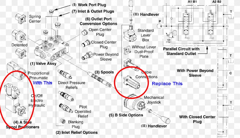
Open center or through center valves need to be connected in series using power beyond porting. Power Beyond allows unused flow to power multiple valve sets downstream. Power beyond also allows the designer to choose which valve sections are more important than another. In a hydraulic system, there can be multiple operator locations.

sebelum memilih hidrolik katup spool directional, Itu harus yakin untuk memilih spool valve sesuai di posisi netral sesuai kebutuhan dari sistem hidrolik. Sebagai contoh: 1. Tekanan desain bongkar sirkuit dengan fungsi spool dalam posisi netral untuk mencapai penghematan energi. Ketika H, F dan G jenis spool dalam posisi netral 4way, 3postion directional spool valve, cairan minyak dari hasil ...

Each square section in a directional control valve schematic symbol — called an envelope — represents a position that the valve spool can be in. The arrangement of symbols and arrows inside each envelope tells you how the ports are interconnected when the valve is in that position. Let's look at each of the 3 positions in this valve, in ...

VES Valves PARALLEL HYDRAULIC CIRCUITS OUTLET CONVERSION PORT OPTIONS The most common type of hydraulic circuit is the par-allel circuit. Refer to the parallel circuit diagram. With all valve spools centered, the pump flow will return to tank at low pressure through the open center bypass. When a spool is actuated, the open center bypass is
ROTARY SPOOL VALVES Rotary spool valves also use a spool fitted in a sleeve but in this case the spool is rotated to select the flow paths rather than sliding (figure 7). the cylinder is subjected to a negative ('runaway') load, or decelerating a high inertia load. A valve may therefore have to be selected with a pressure rating higher than the

Spool valves are usually referred to by the nomenclature 3/2 or 5/3 etc., where the first number relates to the number of ports and the second to the number of different spool positions. We hope you enjoyed this short introduction to pneumatic and hydraulic spool valves.
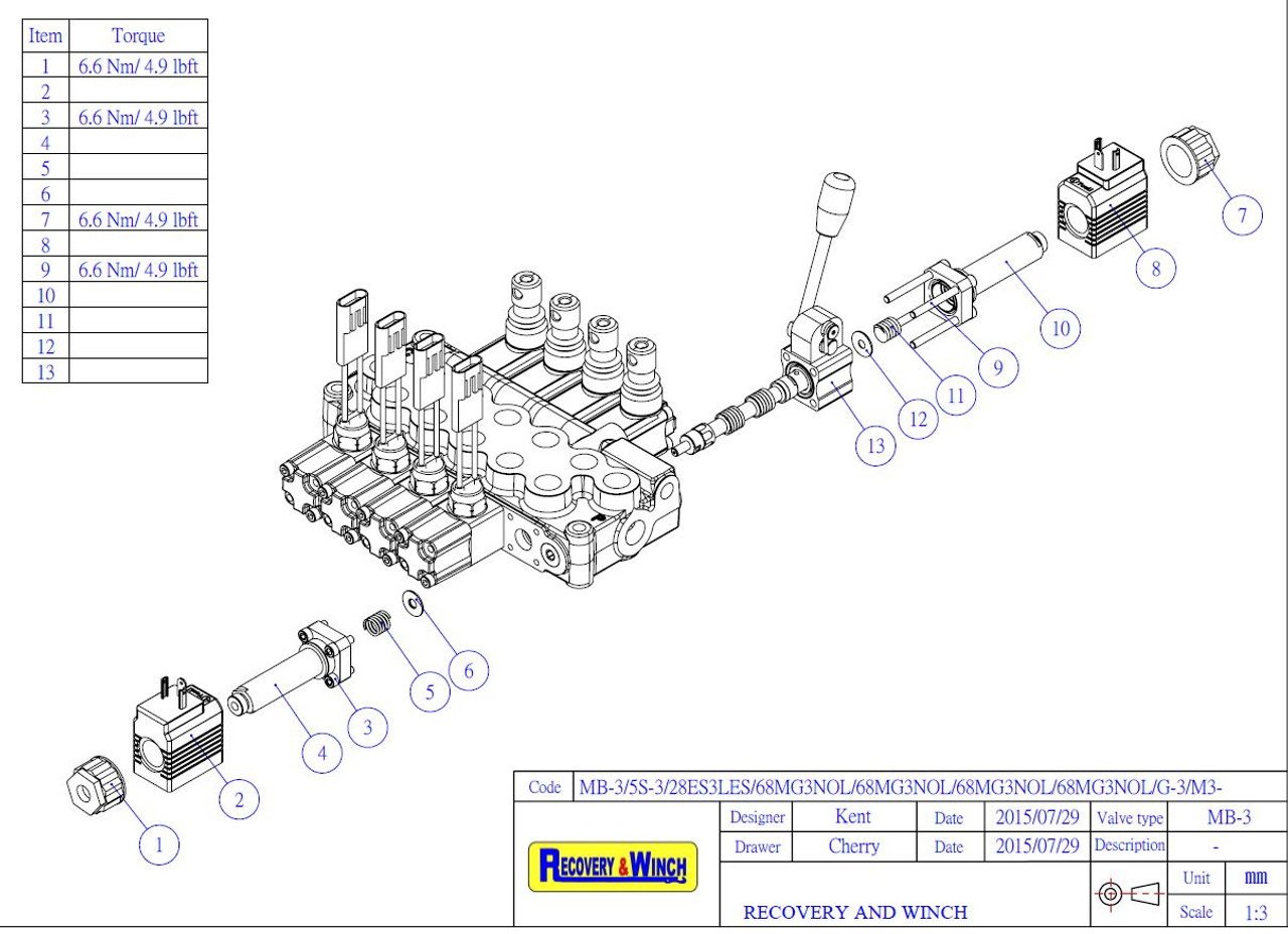
Simple, compact and heavy duty designed monoblock valves from 1 to 6 sections for open and closed centre hydraulic systems. H Fitted with a main pressure relief valve and a load check valve. H Available with parallel or series circuit. H Optional carry--over port (only for parallel circuit). H Diameter 20 mm --0.79 in interchangeable spools.
HYDRAULIC PUMPS 6-9 HYDRAULIC VALVES HYDRAULIC HOSES HYDRAULIC FITTINGS 3 4 5 HYDRAULIC RESERVOIR TANKS 10 POWER TAKE OFF (PTO) 11-12 WET KIT SYSTEMS 13-16 WET KIT ( DUMP TRAILER) QUOTE / ORDER SHEET 17. 8-5-265 Super Dump 73-40-110 SAT Hoist 7-3-120 SAT Hoist Hydraulic Operated Tailgate Lift Cylinder

Hydraulic Spool Valve Diagram Introduction: E -Type Features: In the neutral position , all oil ports closed, not flow . Functional characteristics: 1. The inlet and outlet ports of device are closed, hydraulic actuator can be fixed in any its' working mechanism position, and no movement or rotary further even if there is external force on it ...

Spool Valve Cover Ford 10 40 60 TS TW - PACK OF 2 - PRICE PER UNIT. Spool Valve Cover Ford 10's 40's 60's TS TW. Code: 41919. Loading... Spool Valve Cable. Spool Valve Cable Ford 60 Series TM - Cranked Lever. Spool Valve Cable Ford 60 Series TM. Code: 42037. Loading...

The phantom leak is fixed! Finally!Thank you to Jake Zeigler and CE Smith for the helpProduced with CyberLink PowerDirector 12


0 Response to "40 hydraulic spool valve diagram"
Post a Comment