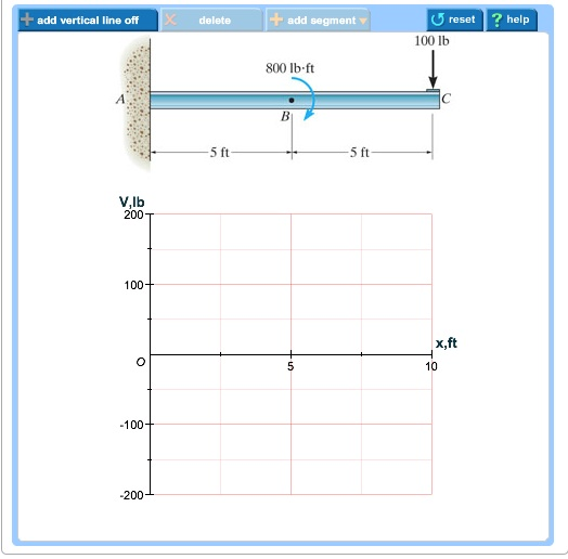
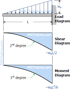
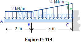
42 draw the shear diagram for the cantilevered beam.
structural analysis problems and solutions. Enter the email address you signed up with and we'll email you a reset link. 20/11/2021 · At points where the shear is zero, the moment is a local maximum or minimum. m kN-Im kN m At x-2. In each problem, let x be the distance measured from left end of the beam to the point under study. 2. Draw shear force diagram (SFD) and bending moment diagram(BMD); 4. 1-77 16. 9 F Grading Weights: Requirement % Value Two in-class exams 32.
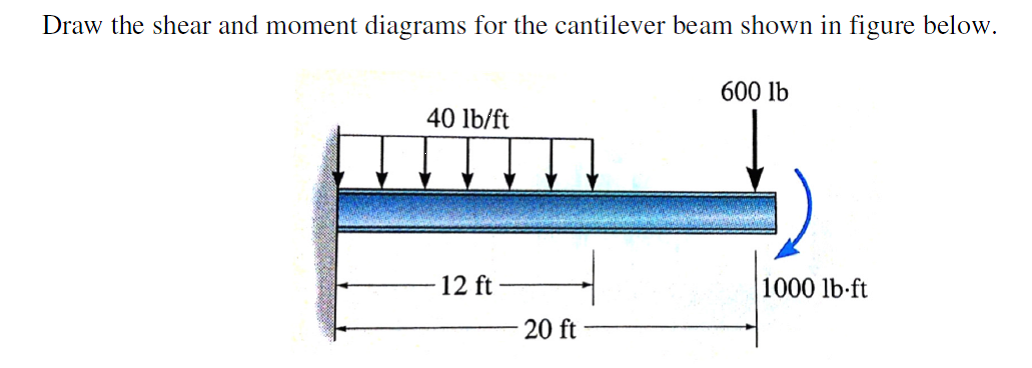
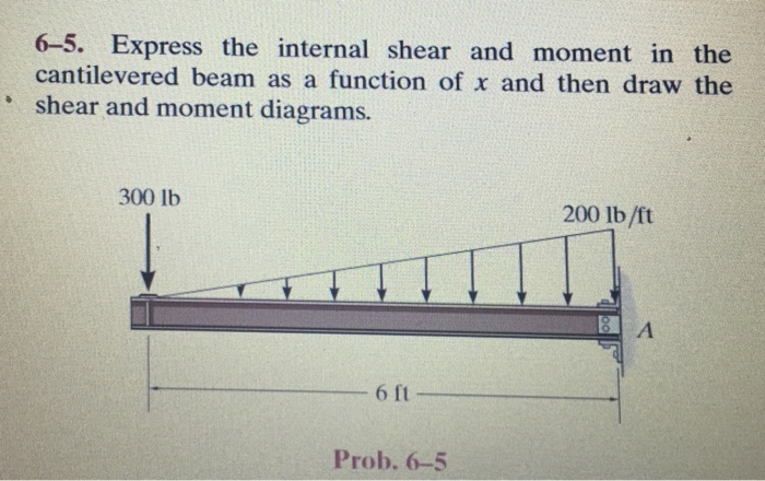
Draw the shear and moment diagrams for the cantilevered beam. 300 lb. 200 lb/ft. A. 6 ft. The free-body diagram of the beam's left segment sectioned through ...
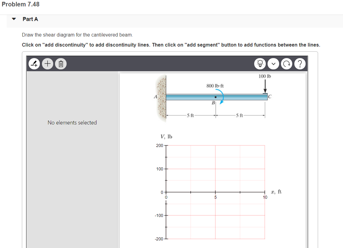
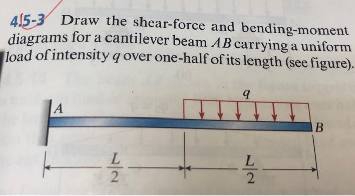
Draw the shear diagram for the cantilevered beam.
Transcribed image text: Two alternative design concepts are to be evaluated for a uniform, single-cell, cantilevered box beam under a distributed load P(x,y) in the positive z direction as shown below. Let each stringer have an area of 0.2 in2 and all skin panels have a thickness of 0.05 in. P(x,y) = p. [1-6)] psi ) = 24 in. 24 in. 1² 24 in. 1 P. ро 24 in. Rib B D Х 3 in. Fixed end 8 in. 8 ... Shear Diagram 9. 5m aオ Figure P2: Beam Question 1: (20 Points) For the beam and loading shown: a- Draw shear and moment diagrams. A free, online multi-span beam calculator to generate shear force diagrams, bending moment diagrams, deflection curves and slope curves for beams with complex boundary conditions, multiple spans and multiple loads ... FREE Answer to Draw the shear force and bending moment diagrams for a cantilever beam as shown in Figure...1 answer · 1 vote: 10 k/m 20KN t1 VD40 kN 80 kN-m = Ceuntreidal dietmee tremm D entroude SF.D At newed dueto UDL sice no lood& acti 8MD 20 KNm 80 KN-m
Draw the shear diagram for the cantilevered beam.. Problem 7 55 part a draw the shear and bending moment diagram of ab beam shear force and bending moment diagram loaded cantilever beam type 1 sfd bmd for ... 1) A cantilever beam of length 2 m carries the point loads as shown in Fig. Draw the shear force and B.M. diagrams for the cantilever beam. Shear Force Diagram. Oct 15, 2014 — To draw a shear force diagram. First find value of shear force between varying loads. Let start from left side. Draw the moment diagram for the cantilevered beam. Click on "add discontinuity" to add discontinuity lines. Then click on "add segment" button to add functions ...
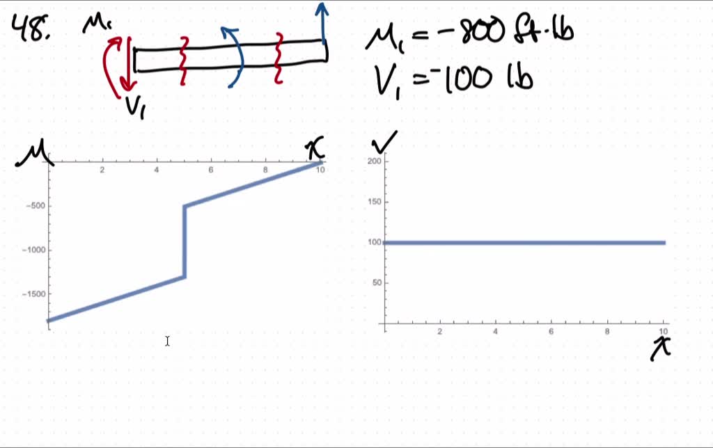
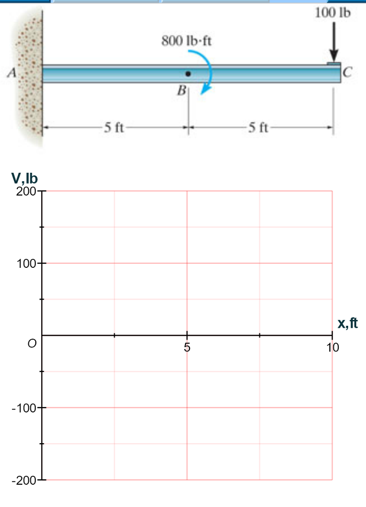
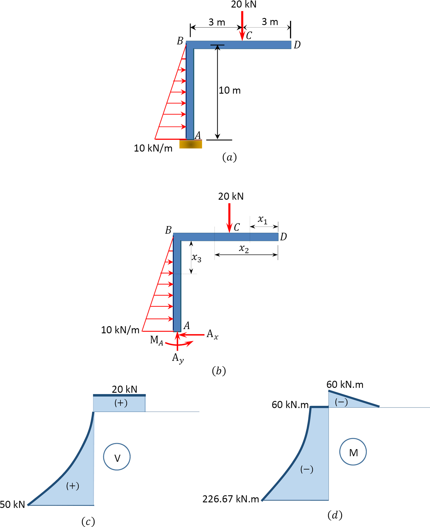
... shear and moment diagrams for the cantilevered beam. ... Draw the shear and bending-moment diagrams for each of the two segments of the compound beam.3 pages 19/11/2021 · 2. P5. (a) Draw the free body diagram (FBD) of the entire beam and calculate the reactions at A. Recall the cantilever beam from the previous section. The beam has a length of 4 meters, width of 0. Fig. ) Express the shear and moment functions in terms of x, and then draw the shear and moment diagrams for the cantilever beam. 3 Mathematical ... 1 answerThe external loads acting on the cantilever beams are : 1) 100 lb force at point C. 2) 800 lb.ft moment at point B. The moment between point B and C... 05/03/2021 · • For cantilevered structures, ... Draw the shear force and bending moment diagrams for the frame subjected to the loads shown in Figure 4.10a. ... The sign convention adopted for shear forces is below. A diagram showing the variation of the shear force …
The area of region 2 of the shear graph is . • The magnitude of the shear at a point equals the slope of the moment diagram at that point. a-) Sketch the beam, showing the loading conditions. m calculates and draw the shear force and bending moment diagrams. For The Figure Below Draw Shear And Moment Diagrams Beam Study. 16/11/2021 · Determine the components of the support reactions at the fixed support a on the cantilevered beam Determine the components of the support reactions at the fixed support a on the cantilevered beam ... The beam shown in the figure below (figure 1) is subjected to a moment of m 30 knm . e. 4(b). M. 5 kN downward (C) 0. 55×10 3 Draw The Shear And Moment Diagram For Cantilever Beam . Express your answer to three significant figures and include appropriate units. and d1 =1. Number of redundant members = m= 2j – 3 = 14 – (16 – 3) = 1. M x = 11. 28/05/2018 · The free-body diagram of the beam’s segment sectioned through the arbitrary points within these two regions are shown in Figs. b and c. Region , Fig. b (1) a (2) Region , Fig. c (3) a (4) The shear diagram shown in Fig. d is plotted using Eqs.
FREE Answer to Draw the shear force and bending moment diagrams for a cantilever beam as shown in Figure...1 answer · 1 vote: 10 k/m 20KN t1 VD40 kN 80 kN-m = Ceuntreidal dietmee tremm D entroude SF.D At newed dueto UDL sice no lood& acti 8MD 20 KNm 80 KN-m
Shear Diagram 9. 5m aオ Figure P2: Beam Question 1: (20 Points) For the beam and loading shown: a- Draw shear and moment diagrams. A free, online multi-span beam calculator to generate shear force diagrams, bending moment diagrams, deflection curves and slope curves for beams with complex boundary conditions, multiple spans and multiple loads ...

01 Draw The Shear Force And Bending Moment Diagrams For The Following Cantilever Beam 10 Marks Homeworklib
Transcribed image text: Two alternative design concepts are to be evaluated for a uniform, single-cell, cantilevered box beam under a distributed load P(x,y) in the positive z direction as shown below. Let each stringer have an area of 0.2 in2 and all skin panels have a thickness of 0.05 in. P(x,y) = p. [1-6)] psi ) = 24 in. 24 in. 1² 24 in. 1 P. ро 24 in. Rib B D Х 3 in. Fixed end 8 in. 8 ...

Shear Force And Bending Moment Diagram For Cantilever Beam With Point Load Mechanical Engineering Concepts And Principles
Engg1300 Assignmentbending Docx Engg1300 Fundamental Mechanics Assignment On Bending Effects Answer All Questions Q1 Draw The Shear Force And Bending Course Hero
Beam And It S Type Beam Beam Is A Structural Member Of Which One Dimension Is Considerably Larger Than Other Two Dimension And Accociated With Loads Suorts Tyes Of Beam Simply Supported Beam If The Ends Of A Beam Are Made To Rest Freely On Supports

Solved Problems 6 4 Bending Mechanics Of Materials By R C Hibbeler Draw Shear And Moment Diagram For The Cantilever Beam Civil Engineering Soft Studies

Solved Book Problems F6 2 Bending Mechanics Of Materials By R C Hibbeler Express The Shear And Moment Functions In Terms Of X And Then Draw The Shear And Moment Diagrams For The

Sketch The Shear And Bending Moment Diagrams For The Cantilever Beam Shown Given The Following Parameters Omega A L Study Com

Bmd Sfd Diagram Sfd Bmd Gate Previous Year Question With Solution Strength Of Materials Mechanical Engineering Pusat Penjualan Ikan Import Di Jakarta

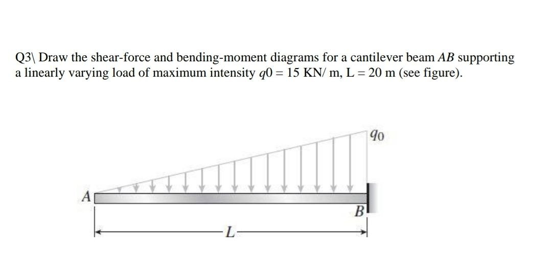
Draw The Shear Force And Bending Moment Diagrams For A Cantilever Beam Ab Acted Upon By Two Different Load Cases A A Distributed Load With Linear Variation And Maximum Intensity Q O See Figure P

A Cantilever Beam Ab Is Subjected To Uniformly Distributed Load As Shown In Figure Ex 3 Determine A Reactions At Supports A And B Draw The Shear Force And Bending Moment Diagrams











0 Response to "42 draw the shear diagram for the cantilevered beam."
Post a Comment