41 hopkins breakaway wiring diagram
Break Away Hopkins Breakaway System Electric Brake Caravan Trailer - Trailer Breakaway Box Wiring Diagram by Bismillah 7-Pin Connector This Trailer Breakaway Box Wiring Diagram version is much more acceptable for sophisticated trailers and RVs. Break Away Hopkins Breakaway System Electric Brake Caravan Trailer - Trailer Breakaway Box Wiring Diagram by Bismillah Trailer Breakaway Box Wiring Diagram - Folks comprehend that trailer is a vehicle comprised of rather complicated mechanisms.
The Engager Breakaway System Wiring Diagram. The Engager™ Break-Away System is designed to bring trailers safely to a stop by activating electric brakes, should a trailer be disconnected while driving. Buy Hopkins Engager Break Away Kit with LED Battery Monitor: Brake Controls - schematron.org FREE Good wiring diagram makes install fairly ...
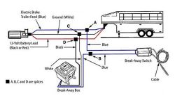
Hopkins breakaway wiring diagram
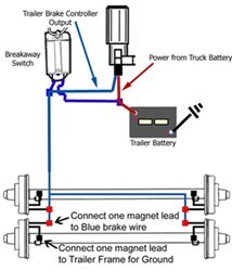
Hopkins Manufacturing Corporation BrakeBuddy.com 1-800-470-2287 INSIDE THE BOX ... Break-Away Switch 8 feet of wire 8 feet of wire 4 feet of wire 4 feet of wire BRAKEBUDDY® UNDER TOWED VEHICLE HOOD WIRING PLEASE FOLLOW THIS DIAGRAM TO INSTALL BRAKEBUDDY® AND GET READY TO TOW NOTE: If there is ANY shipping damage, immediately call BrakeBuddy ... The Hopkins Engager Break Away System changes the way you protect your trailer investment. Hopkins engager wiring diagram. Hopkins offers a variety of towing solutions including vehicle wiring kits adapters vehicle and trailer connectors breakaway systems and much more. 1999 Gem E825 Wiring Diagram. Np261 Transfer Case Diagram. The black wire from the break away switch will connect to the blue wire from the break away box, as shown in the provided diagram. By 'brake wires' I'm assuming you're speaking of the wires connected to the brake magnets on your brake assemblies. One wire exiting the brake magnet could connect to the brake output circuit, usually a blue wire ...
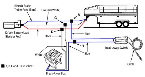
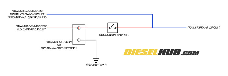
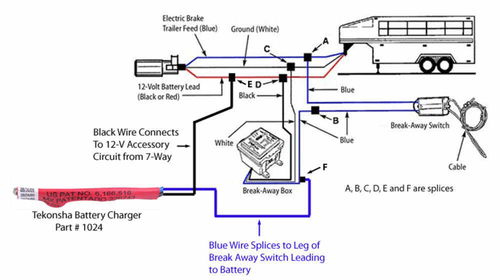
Hopkins breakaway wiring diagram. Hopkins Trailer Brake Control Wiring Diagram . November 19, 2020 1 Margaret Byrd . 0 . Trailer brake control wiring diagram guides what are the standard controller hopkins to stop 7 pole and 4 travel cheap for breakaway manual reliance u haul. Trailer Brake Control Wiring Diagram ... 2. Connect the black (labeled battery) wire of the Break-Away Switch to the blue wire (labeled brake) from the Break-Away Box 3. Splice white wire from Break-Away Box to existing ground wire on trailer or ground directly to trailer frame 4. Splice black wire on Break-Away Box to trailer 12-Volt auxiliary power lead. Through the thousands of images on-line with regards to trailer breakaway switch wiring diagram, we all picks the very best collections having best resolution only for you, and this images is actually among photos selections within our very best photos gallery regarding Trailer Breakaway Switch Wiring Diagram.I hope you will think it's great. This particular graphic (Hopkins Breakaway Wiring ... Trailer Breakaway Wiring Diagram - People comprehend that trailer is a vehicle comprised of quite complicated mechanisms. This car is designed not only to travel 1 location to another but also to take heavy loads. This guide will be talking trailer breakaway wiring diagram.Which are the advantages of knowing these understanding?
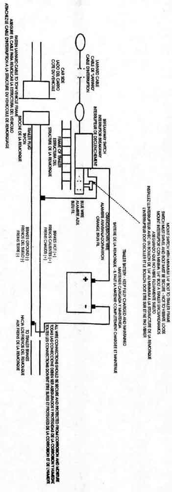
Hopkins 7 Pin Trailer Wiring Diagram - People today understand that trailer is a car comprised of rather complicated mechanics. This automobile is designed not just to travel 1 place to another but also to carry heavy loads. This article will be talking hopkins 7 pin trailer wiring diagram.Which are the benefits of understanding these knowledge? on Hopkins Breakaway System Wiring Diagram. These systems will require the battery be fully charged, by a trickle charger, before use. WIRING DIAGRAM ON BACK. CABLE INSTALLATION. FIG 1. FIG 2. BREAK AWAY HOPKINS BREAKAWAY SYSTEM ELECTRIC BRAKE CARAVAN TRAILER THE ENGAGER B. FREE FAST FREIGHT* GENUINE HOPKINS. wiring. Image of the Hopkins Trailer Breakaway Kit with Battery, Pin Switch and Cable. The battery on the trailer needs power to keep it charged, so it does wire into the trailer electrical system. If something bad happens and the trailer comes loose, pulling the pin connects the battery to the trailer brakes to hopefully avert disaster. Hopkins breakaway wiring diagram. The Trailer Breakaway Kit And How To Use It Mechanical Elements Breakaway Kit Installation For Single And Dual Brake Axle Hopkins Plug In Wiring Kit Dodge Dakota Ram Pickups 42115 Bb005 Low Power Communications Transmitter User Manual Tekonsha Breakaway System With Battery Box Battery Charger And Switch ...
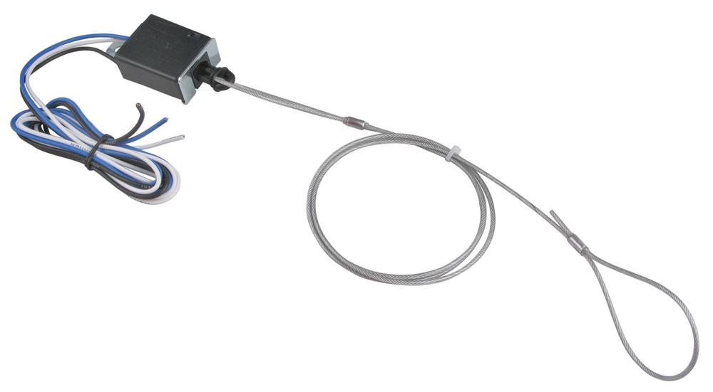
Wiring Adapters. Prevent the need to rewire a vehicle or trailer. Simply plug in one of Hopkins' trailer wiring adapters and start towing! Trailer Wiring Connectors. Whether you are replacing the trailer connector or rewiring the entire trailer, find the Hopkins trailer wiring solution for you! Trailer Break-Away Kits The Engager™ Break-Away System is designed to bring trailers safely to a stop by activating Follow "Wiring Installation". WIRING DIAGRAM ON BACK. Hopkins Engager Push-To-Test Trailer Breakaway Kit w/ Built-In Charger - Side Wiring Diagram for the Curt 4 Pole to 7 Pole Adapter # C And Wiring for . WIRING INSTRUCTIONS: 1. Hopkins Trailer Breakaway Wiring Diagram / Hopkins Wiring Diagram For Gmc Schematic Wiring Diagram Across1a Across1a Shiatsuinrete It / 7 wire trailer circuit, 6 wire trailer circuit, 4 wire trailer circuit and other trailer wiring diagrams.. In the north american market it is very common for brake lights and turn signals to be combined. Code: HM20060. Retail: $28.02. Price: $15.53. Accessories and Parts. Trailer Breakaway Kit. Switch. Hopkins. As a crucial component to a trailer breakaway system, this breakaway switch activates the trailer brakes should the trailer become disconnected from your tow vehicle. 48" Long breakaway cable and 44" long installation wires.
Wiring Guides. NOTE: Identify the wires on your vehicle and trailer by function only. Color coding is not standard among all manufacturers. *Refer to product instructions and locate wires on vehicle by function only. Not all vehicles are listed obove. Recommended use with 47295 and 47285.
Hopkins Impulse Brake Controller Wiring Diagram - wiring diagram is a simplified welcome pictorial representation of an electrical circuit. It shows the components of the circuit as simplified shapes, and the capability and signal connections amid the devices. A wiring diagram usually gives recommendation very nearly the relative position and ...
Hopkins Breakaway Kit with a Built-in Charger. Hopkins breakaway kits with built-in chargers require four connections. One connection has already been made inside the battery box. The following diagram shows a typical wiring configuration for a Hopkins breakaway kit with a battery charger.
Hopkins Engager Push-To-Test Trailer Breakaway Kit w/ Built-In Charger - Side Wiring Diagram for the Curt 4 Pole to 7 Pole Adapter # C And Wiring for . Hopkins Engager Trailer BreakAway Kit Installation review and We have the pre-installed wires, our ground, power, and break-V. Built into.
About Press Copyright Contact us Creators Advertise Developers Terms Privacy Policy & Safety How YouTube works Test new features Press Copyright Contact us Creators ...
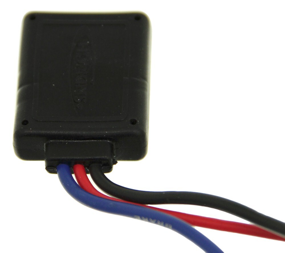
You are correct, the Hopkins LED Breakaway Switch, # HM, does have 3 wires. The white wire is the ground wire and should be attached to the trailer.WIRING DIAGRAM ON BACK CABLE INSTALLATION FIG 1 FIG 2 FIG 3 CABLE CABLE CABLE BREAK-AWAY SWITCH BREAK-AWAY SWITCH BREAK-AWAY SWITCH BUMPER CLEVIS SAFETY CHAIN POCKET PIN Break-Away Switch Setup 1.
7-Pin Connector. This Hopkins 7 Blade Trailer Connector Wiring Diagram model is far more suitable for sophisticated trailers and RVs. It can transfer electricity better compared to the connector is suggested for higher-level electric in the car. Here is the diagram for 7-pin connector. White Pin for the ground.
Hopkins trailer brake controller wiring guides 2008 dodge ram electric diagram breakaway kit installation for single. This article will be discussing impulse trailer brake controller. These instructions will likely be easy to grasp and implement. Prevent the need to rewire a vehicle or trailer. Trailer, then splices into its wiring and connects ...
1. Helpful Expert Reply: I have attached the installation instructions for the Hopkins Engager Trailer BreakAway Kit, part # 20099. This kit includes a charger and an LED tester and will work with single and tandem axle trailers. I have also attached a link to an installation video for this kit you can check out.
1. Splice one blue wire of the Break-Away Switch to the electric brake wire coming from the trailer side connector (A - see diagram on next page). 2. Connect other blue wire of Break-Away Switch to the blue wire (labeled "Brake") from the Break-Away box (B). (Note: Blue wires are interchangeable on the Break-Away Switch.) 3.
1.Mount Break-Away Switch (A) close enough on trailer that cable can be attached to vehicle. 2.Splice the blue wire of the Break-Away Switch to the electric brake wire coming from the trailer side connector. 3.Connect the black wire of Break-Away Switch to the blue wire of the Break-Away Box. Locate wires by function only. Color coding
The black wire from the break away switch will connect to the blue wire from the break away box, as shown in the provided diagram. By 'brake wires' I'm assuming you're speaking of the wires connected to the brake magnets on your brake assemblies. One wire exiting the brake magnet could connect to the brake output circuit, usually a blue wire ...
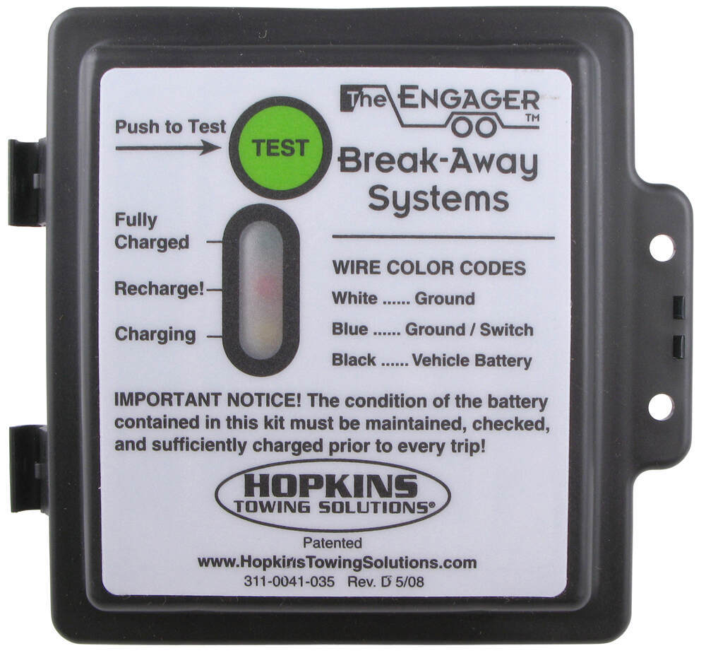
Replacement Lid For Hopkins Engager Break Away Kit With Led Charge Indicator And Sticker Hopkins Accessories And Parts 20106
The Hopkins Engager Break Away System changes the way you protect your trailer investment. Hopkins engager wiring diagram. Hopkins offers a variety of towing solutions including vehicle wiring kits adapters vehicle and trailer connectors breakaway systems and much more. 1999 Gem E825 Wiring Diagram. Np261 Transfer Case Diagram.
Hopkins Manufacturing Corporation BrakeBuddy.com 1-800-470-2287 INSIDE THE BOX ... Break-Away Switch 8 feet of wire 8 feet of wire 4 feet of wire 4 feet of wire BRAKEBUDDY® UNDER TOWED VEHICLE HOOD WIRING PLEASE FOLLOW THIS DIAGRAM TO INSTALL BRAKEBUDDY® AND GET READY TO TOW NOTE: If there is ANY shipping damage, immediately call BrakeBuddy ...
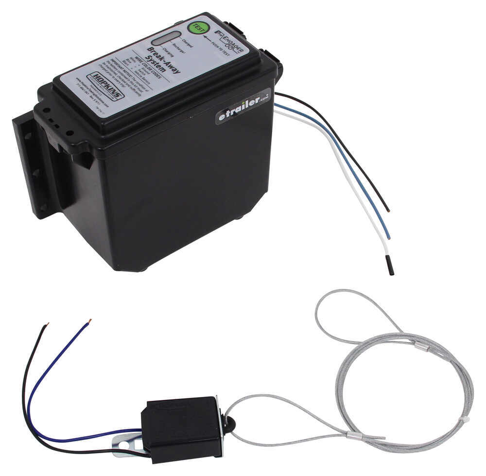
Hopkins Engager Push To Test Trailer Breakaway Kit With Built In Battery Charger Top Load Hopkins Trailer Breakaway Kit 20400
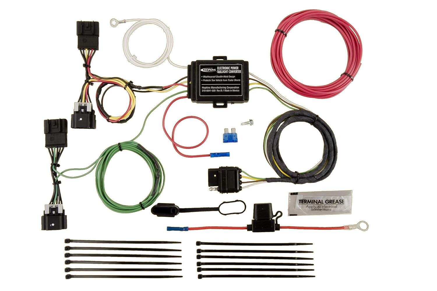
Hopkins 41300 Vehicle Wiring Kit Hopkins Towing Solutions Exterior Accessories Towing Products Winches Acvisas Com

7 Way Rv Style Trailer Plug Diagram Truck Side Trailer Light Wiring Trailer Wiring Diagram Truck And Trailer

Amazon Com Curt 52040 Soft Trac 1 Trailer Breakaway Switch Kit System With Battery And Charger Automotive














0 Response to "41 hopkins breakaway wiring diagram"
Post a Comment