41 fire alarm tamper switch wiring diagram
This functionality makes flow switches an integral part of automated fire alarm systems as they do not require a user to pull down the fire alarm switch. On the other hand, tamper switches try to ensure that human interaction with the fire suppression system, like partial or full closure of the sprinkler system valves, is detected and an alarm ... This cover tamper switch mounts to all System Sensor ... National Fire Alarm Code. NFPA 13: ... 1) Wire as required per wiring diagram (Figure 2), placing.2 pages
listed fire alarm power supply Wiring Information Refer to reference diagrams on pages 3 and 4 Wire Connections Screw terminals for in/out wiring, 18 to 12 AWG wire Address Means DIP switch, 8 position Temperature Range 32° F to 120° F (0° C to 49° C) intended for indoor operation Humidity Range Up to 85% RH at 86° F (30° C)
Fire alarm tamper switch wiring diagram
NOTE: Refer to the diagram on page 5, and to the Wiring Diagram on the inside of the back cover of this manual for wiring and component identif ication. 1. Remove knockouts from cabinet to accommodate the power input wires, and wiring to the fire panel. Then mount the cabinet securely to the wall using 4 screws or bolts. When connecting sprinkler tamper switches, I have found that the best way to make sure the system is going to work correctly is to: Follow the fire alarm manufacturer's installation sheet exactly. These sheets show the correct wiring. DO NOT USE the labels on the switch inside the tamer switch assembly. Half of the time those labels are wrong. After installation, put the battery and switch on the main breaker to check if it works properly. Related Post: Difference Between Conventional and Addressable Fire Alarm; Wiring Diagram of Heat Detector in Home (AC) Conventional Fire Alarm System.
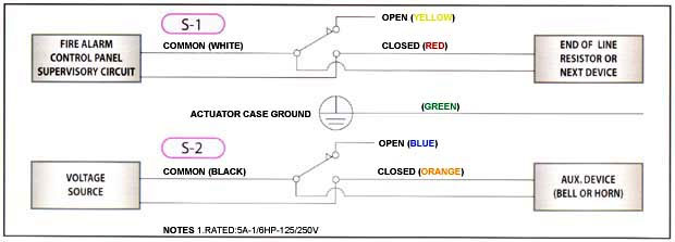
Fire alarm tamper switch wiring diagram. LISTED FIRE ALARM. CONTROL PANEL. SUPERVISORY CIRCUIT. WIRING DIAGRAM ... NOTE: Valves incorporating supervisory tamper switches are for indoor and outdoor ...1 page National Fire Alarm Code: NFPA-72 Contact Ratings Two sets of SPDT (Form C) 10.0 A, ½ HP @ 125/250 VAC ... WFD Field Wiring Diagram Ordering Information ... 546-7000 Tamper-proof switch kit WFDW Tamper-proof wrench for cover WFDN4 Gasket kit WIRING DIAGRAM (SWITCH POSITION VALVE FULL OPEN) SWITCH 1: DUAL LEADS BLACK LISTED FIRE ALARM CONTROL PANEL SUPERVISORY CIRCUIT TO NEXT INDICATOR OR END OF ... Fire alarm tamper switch wiring diagram. Sprinkler tamper switch wiring diagram.14.06.2020 · on the other hand, tamper switches try to ensure that human interaction with the fire suppression system, like partial or full closure of the sprinkler system valves, is detected and an alarm is triggered.
Fire Alarm Flow Switch Wiring Diagram. Variety of fire alarm flow switch wiring diagram. A wiring diagram is a streamlined conventional pictorial representation of an electric circuit. It shows the elements of the circuit as simplified shapes, as well as the power as well as signal links between the devices. A wiring diagram normally offers details… Valve Supervision (Tamper Switch) Selection Guide Fig. ... Four Wire Smoke Detector - A smoke detector which initiates an alarm condition on two separate ...118 pages Water Flow, Backflow, OSY, Tamper Switch The #1 website for NICET Practice Tests, NICET study guides, Fire Alarm Code Knowledge, and General Fire Alarm Topics. We have up to date information on the newest fire alarm trends such as fire service access elevators, mass notification, voice intelligibility, occupant evacuation elevators and two-way ... d. indicate all fire alarm devices and equipment on plans, wiring diagrams, calcualtions showing secondary supply and voltage drop, and response points. ... fire alarm connection to tamper switch fire alarm connection to flow switch fire alarm relay 3p/60a nema 0 shown size 3-pole, 60 amp, nema 0 rated
Sprinkler Flow Switch Wiring Diagram Collection. sprinkler flow switch wiring diagram - Just What's Wiring Diagram? A wiring diagram is a kind of schematic which utilizes abstract pictorial symbols to reveal all the affiliations of components in a system. Circuitry diagrams are made up of two things: signs that represent the parts in the circuit, and… Kidde Smoke Detector Wiring Diagram. By | December 8, 2014. 0 Comment. Quick connect harness 21027590 by kidde smoke alarm interface code one detector hardwired with 9 volt battery backup 6 pack 21006373 the lithium led lights replacement alert online in greece b00pc5sx98 operation and testing fire 1275h user manual page 4 7 original mode 11407 ... Dimension: 2339 x 1654. DOWNLOAD. Wiring Diagram Images Detail: Name: fire alarm flow switch wiring diagram - Water Flow Switch Wiring Diagram Tamper and Flow Switch Wiring Diagrams Lovely Bep2 Od Bioentry. File Type: JPG. Source: magnusrosen.net. Size: 326.83 KB. Dimension: 1032 x 1687. Indicating Appliance Circuits connect the fire alarm panel to the components which alert building occupants of the fire, i.e., bells, horns, speakers, strobe lights, etc. The following illustrations show schematics, wiring connections, riser diagram, and wire pull, for some commonly used fire alarm circuits.
For A Switch Detect This Error Sdm Magazine
automatic sprinkler system valve tamper supervisory switch in series with a fire alarm initiating device circuit in such a manner that the operation of the tamper switch will produce a "trouble signal." And yet, this issue rises to the surface time and time again. It seems that this "easy way out" tempts many fire alarm installers.

Engineering Teknologi Dan Agribisnis 3 Kesalahan Instalasi Smoke Detector Dan Flow Switch
3. see plans for location and quantities of fire alarm devices. all horn and strobes shall be wired on alternate circuits. 4. all wiring to fire alarm devices shall be teflon coated approved for fire alarm system. run #14awg minimum exposed in accessible ceiling area. otherwise run in 3/4" emt conduit. 5.
Flow Switch And Bell Wiring Electrician Talk
fire alarm flow switch wiring diagram - Water Flow Switch Wiring Diagram Tamper and Flow Switch Wiring Diagrams Lovely Bep2 Od Bioentry. File Type: JPG. Source: magnusrosen.net. Variety of fire alarm flow switch wiring diagram. Click on the image to enlarge, and then save it to your computer by right clicking on the image.

Fire By Jules Bartow Technology In The Vein Is It Creepy Or Cool Culture Critic
Name: fire alarm flow switch wiring diagram - Fire Alarm Tamper Switch Wiring Diagram Elegant Alarm Flow Switch Wiring Diagram Get Free Image About; File Type: JPG; Source: kmestc.com; Size: 39.83 KB; Dimension: 415 x 513

Nx Reliance Installer Manual Cheat Sheet Securefind
Fire Alarm Flow Switch Wiring Diagram Download. fire alarm flow switch wiring diagram - A Novice s Overview to Circuit Diagrams A first look at a circuit representation may be confusing, but if you can review a train map, you could read schematics. The purpose is the same: obtaining from factor A to point B. Literally, a…
Nni Inc Fire Protection Butterfly Valves
2 FireLite SLC Wiring Manual — P/N 51309:R3 7/29/2019 Fire Alarm & Emergency Communication System Limitations While a life safety system may lower insurance rates, it is not a substitute for life and property insurance! An automatic fire alarm system—typically made up of smoke detectors, heat detectors, manual pull stations, audible warning

Gate Valve Wiring R Firealarms
Note: The bottom mounting holes are used to mount the switch on the other side of the cabinet. 3. Set the tamper switch on the screw studs and fa sten the tamper switch to the back box with the two number six flange nuts provided. Figure 1. Tamper Switch Wiring Procedure Refer to Figure 2 and the notes for wiring instructions. Figure 2.

What Is A Tamper Switch For Fire Protection Systems
zone. Combination circuits allow waterflow switches and their associated valve tamper switches to be connected on a common two-wire IDC. FireShield panels are available in three sizes and can be ordered with or without the optional DACT: FS302 - The three-zone FS302 is ideal for use as a sprinkler supervisory panel.
.jpg)
Water Flow Backflow Osy Tamper Switch Fire Alarms Online
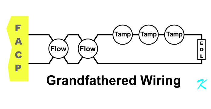
Supervisory wiring is the new, common "Use-the-Tamper-Switch-to-Short-Out-the-Wires" method that sends a supervisory alarm to the fire alarm panel when the valve is tampered with. If you determine that it's a Supervisory Tamper, use the diagrams in the manual for the panel.

Como Conectar N Tamper Switch Edward System Fire Alarm Youtube
A tamper switch is a mechanical and electrical device connected to a fire protection valve that signals a warning if the valve partially or fully closes. Regardless of the type of tamper switch, they all function similarly. The tamper switch features an actuating unit, usually a lever or cable with a resting position.
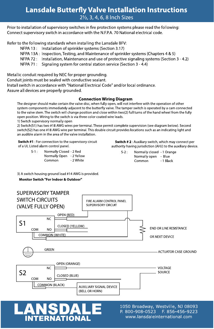
Lansdale Butterfly Valve Installation Instructions Manualzz
Supervisory / tamper switch voltage and current ratings: S.P.S.T. - for valve position supervisory / tamper indication used with U.L. listed fire alarm ...

Fire Protection Sprinkler System Designs Fire Sprinkler System Fire Protection Fire Hydrant System
The cover tamper switch can be wired into the plug circuit or wired as a separate circuit. (See wiring diagrams.) Testing The PTS-C and its associated protective monitoring system should be tested in accordance with applicable NFPA codes and standards and/or the authority having jurisdiction (manufacturer recommends quarterly or more frequently).

Cover Tamper Switch
I Need To Wire A Vsr Flow Switch And Fire Both Items Using 24v Have Step Down Transformer From 120v If. Install an alarm bell back box and the fire to my house is bells installation sheet how rm4 smart relay manualzz firing wiring diagram for android 11ma 24vdc mbf 6ev 24 b6 b10 bb wp doorbell diagrams circuit instructions 120v water motor gongs china 24v conventional electric construction ...
Connection
Sprinkler Tamper Valve Wiring Diagram. Fire alarm tamper switch wiring diagram why does closing some gatevalves show kelco flow full how do i connect a ul wafer type erfly valve z tide nni inc protection valves wfsr f waterflow with grooved gemlockgrooved lansdale erfly installation sprinkler integration 20. Fire Sprinkler Alarm Integration 20 ...
2
Tamper Proof Security System / Burglar Alarm Wiring ... The circuit below is an over simplified example of a Normally Open alarm circuit. When the switch is open under normal conditions the circuit is incomplete and the siren will not sound. When the switch is closed then the circuit becomes complete. ... These diagrams show a simplistic ...

Butterball Wiring Diagram Manualzz
After installation, put the battery and switch on the main breaker to check if it works properly. Related Post: Difference Between Conventional and Addressable Fire Alarm; Wiring Diagram of Heat Detector in Home (AC) Conventional Fire Alarm System.
How Alarm Works And Installation Tips
When connecting sprinkler tamper switches, I have found that the best way to make sure the system is going to work correctly is to: Follow the fire alarm manufacturer's installation sheet exactly. These sheets show the correct wiring. DO NOT USE the labels on the switch inside the tamer switch assembly. Half of the time those labels are wrong.
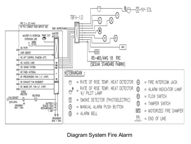
Fire Alarm
NOTE: Refer to the diagram on page 5, and to the Wiring Diagram on the inside of the back cover of this manual for wiring and component identif ication. 1. Remove knockouts from cabinet to accommodate the power input wires, and wiring to the fire panel. Then mount the cabinet securely to the wall using 4 screws or bolts.

Integrasi Hydrant System Ke Fire Alarm System
Module E Part 1 Electrical Exam Prep Canada

Fire By Jules Bartow Technology In The Vein Is It Creepy Or Cool Culture Critic

Cara Mudah Konek Flow Switch Dan Tamper Switch Amfun Cees Youtube
2
2
Eol In Series Diynot Forums

G Sprinkler Easy Way To Wire Valve Tamper Youtube
Fire Alarm

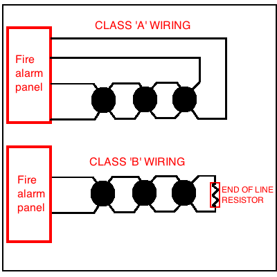
Class B Fire Alarm Wiring Doityourself Com Community Forums

Intro To Basic Fire Alarm Technology Ppt Download

Wiring A Zonecheck Addressable Flow Switch Youtube
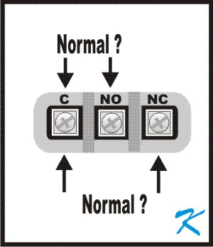
Does The N O Mean Normally Open Or Normally Closed On A Tamper Switch

Fire Alarm Flow Switch Wiring Diagram Blender Kita

Instalasi Fire Alarm Konvensional Jogja Safety
2

What Is A Tamper Switch For Fire Protection Systems

Basic Types Of Sprinkler Systems Fire Alarm General Discussion The Fire Panel Forums
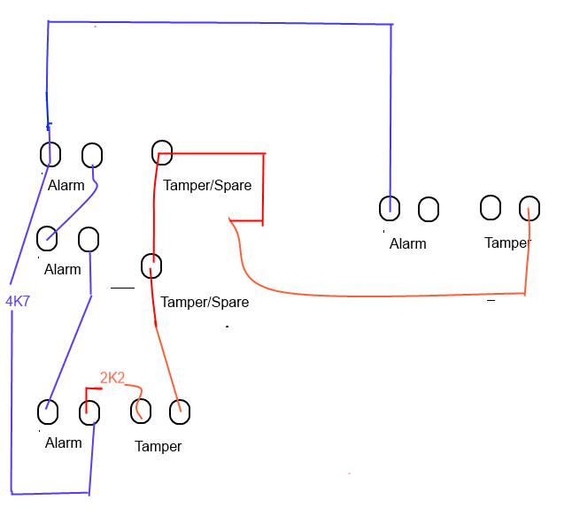
Can A Waterflow Switch And A Tamper Switch Be On The Same Zone

Install An Alarm Bell Back Box And Bell Guard In 6 Easy Steps
2
2

Fire Alarm System Wiring Diagram 10 Addressable Car Harness New Fire Alarm System Fire Alarm Alarm System
0 Response to "41 fire alarm tamper switch wiring diagram"
Post a Comment